

Description
Hard-Numbers: Technical Specifications
- Number of Axes: 4 servo valve axes
- Valve Type: Electro-hydraulic servo valve (2-coil differential or single-coil)
- Output Current Range: 0-40 mA per coil, ±20 mA differential
- Current Resolution: 12-bit (0.01 mA step size)
- Position Loop Bandwidth: 20 Hz typical (up to 50 Hz programmable)
- Current Loop Update Rate: 1 kHz per axis
- Position Feedback: LVDT (Linear Variable Differential Transformer), Resolver, or 4-20 mA
- Feedback Resolution: 14-bit LVDT (0.01% full scale)
- Safety Rating: IEC 61508 SIL 3 capable (dual-channel architecture)
- Diagnostics: Built-in coil integrity monitoring, position feedback health, watchdog timer
- Isolation: 1500V RMS between valve outputs and backplane
- Module Power Draw: 4.0A @ 5VDC from backplane
- Backplane Current: 5V: 4.0A max
- Operating Temperature: -20°C to 70°C (-4°F to 158°F)
- Storage Temperature: -40°C to 85°C (-40°F to 185°F)
- LED Indicators: PWR, OK, FAULT, individual axis status LEDs, SAFETY (SIL status)
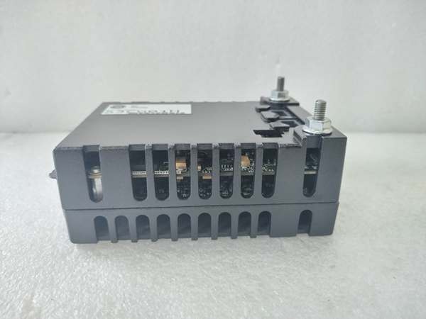
- Cooling: Forced air (requires Mark VIe backplane cooling)
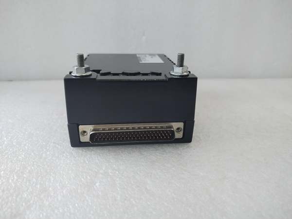
- Field Termination: Standard 50-pin terminal block (GE part number IS200PSCAH1B)
- Module Slot: Mark VIe I/O backplane (any slot in control rack)
- Communication: Backplane via TCP/IP (embedded PSC processor)
- Firmware Version: Compatible with Mark VIe v7.0 and later
- Fault Response: Configurable failsafe valve closure on fault (SIL 3 safe state)

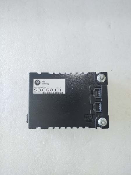
GE IS220PHRAH1A
The Real-World Problem It Solves
Servo valves require precise, high-speed control for turbine applications. The IS220PSCAH1B delivers 4 axes of closed-loop servo valve control with 20 Hz bandwidth and SIL 3 safety capability, ensuring your fuel valves, governor valves, and anti-surge valves respond accurately and safely to control commands.
Where you’ll typically find it:
- Gas turbine fuel valve control systems (multiple fuel valves)
- Steam turbine governor valve control racks
- Compressor anti-surge valve control with safety protection
Bottom line: It gives you multi-axis servo control with SIL 3 safety for critical valve actuation.
Hardware Architecture & Under-the-Hood Logic
The IS220PSCAH1B is a high-performance servo controller module for Mark VIe turbine control racks. Each of the 4 axes has dedicated current loop controller, DAC (Digital-to-Analog Converter), and output driver. The module supports dual-coil differential servo valves or single-coil configurations. Position feedback is processed from LVDT, resolver, or 4-20 mA transmitters, providing closed-loop position control at 20 Hz bandwidth. The dual-channel architecture enables SIL 3 safety compliance—each axis has redundant processing paths that compare results and trigger failsafe on disagreement. An embedded ARM processor manages axis configuration, position loop tuning (PID gains), fault detection, and backplane communication. Valve characterization (linearization) compensates for non-linear valve flow characteristics. Fault detection includes coil open circuit, coil short circuit, LVDT loss, position deviation, and watchdog timeout. On fault detection, the module drives valves to the safe position (typically closed) and reports the fault to the main controller.
Internal signal flow:
- Position command from main controller arrives via backplane TCP/IP
- Embedded processor calculates required position setpoint
- Valve characterization linearization applied to command
- Position feedback (LVDT/resolver) provides actual valve position
- Position error calculated and fed to PID controller
- PID output determines required coil current
- DAC converts current command to analog value
- Output drivers amplify to produce 0-40 mA coil current
- Hall effect current sensors measure actual coil currents
- Current feedback compared to command; error drives current loop PI controller
- Dual-channel processing paths compare results for safety (SIL 3)
- Fault detection circuits monitor coils, feedback, and watchdog
- On fault, failsafe logic drives coils to safe position (closed)
- Diagnostic data transmitted to main controller via backplane

GE IS220PHRAH1A
Field Service Pitfalls: What Rookies Get Wrong
Incorrect LVDT calibration causes position errorThe LVDT provides valve position feedback. I’ve seen technicians skip LVDT calibration, resulting in position errors up to 10% and unstable valve response.
- Field Rule: Perform LVDT calibration after any mechanical work or valve replacement. Use the Mark VIe calibration tool to stroke the valve between 0% and 100% while recording LVDT output. Enter the calibration points (0%, 50%, 100%) into the module configuration. Verify position accuracy at multiple points during commissioning. Document calibration values in your maintenance log.
Mismatching coil resistance leads to oscillationEach servo valve has specific coil parameters. I’ve seen technicians install a new valve without updating coil resistance, causing the current loop to become unstable and the valve to oscillate.
- Field Rule: Always measure coil resistance with a multimeter before connecting to the IS220PSCAH1B. Record resistance values and enter them into the Mark VIe valve configuration. Perform autotune after any valve replacement to calibrate the current loop. Document coil resistance values per axis in your asset management system.
Ignoring SIL 3 safety requirements defeats protectionThe SIL 3 architecture requires dual-channel comparison for safety. I’ve seen technicians bypass safety interlocks or disable comparison logic to simplify commissioning, defeating the safety protection.
- Field Rule: Never disable SIL 3 safety comparison logic for commissioning or operation. Configure both processing channels and enable comparison in Mark VIe software. Test failsafe response by simulating a fault (disconnecting LVDT or coil) and verifying both channels agree on safe state. Document SIL 3 testing in your safety validation records.
Improper grounding of LVDT shield causes noise pickupLVDT cables run long distances through high-noise environments. I’ve seen technicians connect the shield at both ends, creating ground loops and 60 Hz noise that corrupts position feedback.
- Field Rule: Use shielded twisted pair cable for LVDT wiring. Terminate the shield at the module end only—never at both ends. Maintain shield continuity throughout the run and use proper shield clamp connectors. If noise persists, consider using differential LVDT amplifiers or remote signal conditioning. Measure LVDT output noise with a portable analyzer—if 60 Hz > 5% of signal, check grounding.
Leaving axes unpowered during commissioning creates undefined behaviorServo valves with no current applied float to spring-return position. I’ve seen technicians commission axes without powering coil current, causing valves to drift to unexpected positions and trigger safety trips.
- Field Rule: Always energize coil current before commissioning servo axes. Verify valve moves to commanded position when current is applied. If a valve must be disabled for service, use the module’s “disable axis” function in Mark VIe software—this drives the valve to a known safe position. Document disabled axis status in your maintenance procedure.
Not tuning PID gains causes sluggish responseDefault PID gains may not match your valve dynamics. I’ve seen operators use factory settings for valves with high inertia, resulting in sluggish response and poor load tracking.
- Field Rule: Perform PID tuning after commissioning. Use Mark VIe’s autotune function as a starting point, then fine-tune based on actual valve response. Increase proportional gain for faster response, reduce if oscillation occurs. Adjust derivative gain to reduce overshoot. Document tuned PID gains per axis in your loop tuning records.
Commercial Availability & Pricing Note
Please note: The listed price is for reference only and is not binding. Final pricing and terms are subject to negotiation based to current market conditions and availability.


