
Description
Hard-Numbers: Technical Specifications
- Protocol Support: Redundant IONet 100Mbps Ethernet
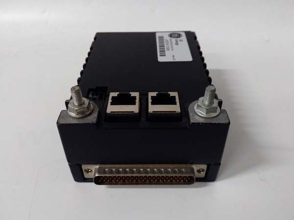
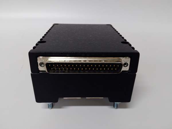
- Port Count: 2× RJ45 Ethernet, 1× DC‑37 field connector
- Input Channels: 8 isolated RTD inputs
- Supported Types: Pt100, Cu100, 3‑wire & 4‑wire configurable
- Isolation Rating: 2500 VAC RMS field‑to‑backplane
- Accuracy: ±0.1°C over operating range
- Max Lead Resistance: 15 Ω per channel
- Power Requirements: 24 VDC ±10%, 8.5 W max draw
- Operating Temperature: 0°C to +65°C
- Hazardous Rating: Class I Div 2, Zone 2, ATEX/IECEx
- Dimensions: 158.75 × 107.95 × 30 mm
- Weight: 0.70 kg
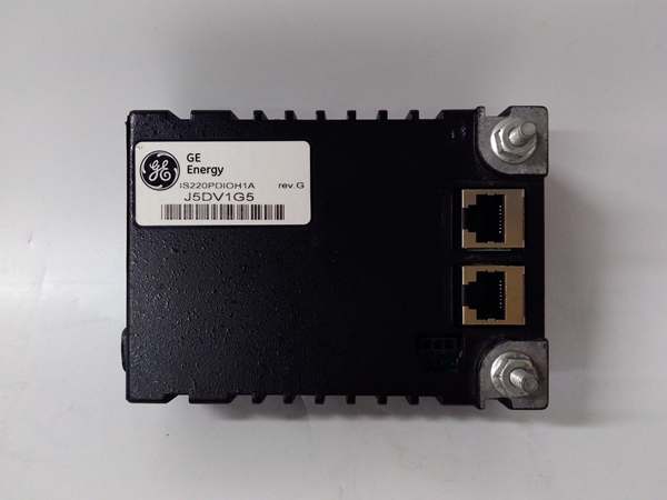
IS220PDIOH1A
The Real-World Problem It Solves
Unisolated temperature inputs suffer ground loops and EMI that drift readings outside tolerance. Separate signal conditioners waste cabinet space and add calibration labor.
Where you’ll typically find it:
- Gas and steam turbine bearing temperature monitoring
- Generator winding and casing RTD sensing
- Compressor lube oil and process temperature loops
Bottom line: provides accurate, isolated RTD measurement while reducing wiring and component count in Mark VIe systems.
Hardware Architecture & Under-the-Hood Logic
uses a dedicated local processor for independent temperature conversion. Full galvanic isolation separates field sensors from backplane and network electronics.
- RTD leads terminate at the DC‑37 field connector.
- Excitation current is applied to sense resistance across the sensor.
- Signals pass through 2500V isolation barriers to eliminate ground loops.
- On‑board ADC digitizes readings with ±0.1°C accuracy.
- Local processor linearizes raw data to engineering units.
- Temperature values transmit over redundant IONet to the controller.
- Diagnostics detect wire break, short, and out‑of‑range conditions.
Field Service Pitfalls: What Rookies Get Wrong
Excessive Lead ResistanceTechs use long, small‑gauge wire that exceeds 15Ω lead resistance. Readings skew low and trigger false under‑temperature alarms.
- Field Rule: Use minimum 24 AWG wire; limit total lead length to avoid exceeding 15Ω per channel.
Dual‑End Shield GroundingGrounding RTD cable shields at both ends creates circulating currents. Temperature readings jump randomly with no physical change.
- Quick Fix: Terminate shield only at the marshalling cabinet; leave the field end ungrounded.
Improper 3‑Wire BalancingUnequal wire lengths in 3‑wire RTD circuits create offset errors. Readings remain consistently off by several degrees.
- Field Rule: Use identical length and gauge for all three RTD leads to maintain balance.
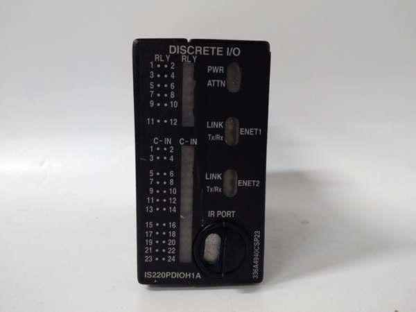
IS220PDIOH1A
Commercial Availability & Pricing Note
Please note: The listed price is for reference only and is not binding. Final pricing and terms are subject to negotiation based on current market conditions and availability.


