
Description
Hard-Numbers: Technical Specifications
- Number of Channels: 16 thermocouple input channels
- Supported Thermocouple Types: Type J, K, T, E, N, R, S, B (software-configurable per channel)
- Input Range: -200°C to 1800°C (depends on thermocouple type)
- Cold Junction Compensation: Automatic, ±0.3°C accuracy
- Accuracy: ±0.5°C typical (±1.0°C maximum) after CJC correction
- Resolution: 16-bit ADC (0.1°C step size)
- Sampling Rate: 10 Hz per channel
- Common Mode Rejection: 80 dB typical at 60 Hz
- Input Impedance: 10 MΩ typical
- Isolation: 1500V RMS between channels and backplane
- Module Power Draw: 2.8A @ 5VDC from backplane
- Backplane Current: 5V: 2.8A max
- Operating Temperature: -20°C to 70°C (-4°F to 158°F)
- Storage Temperature: -40°C to 85°C (-40°F to 185°F)
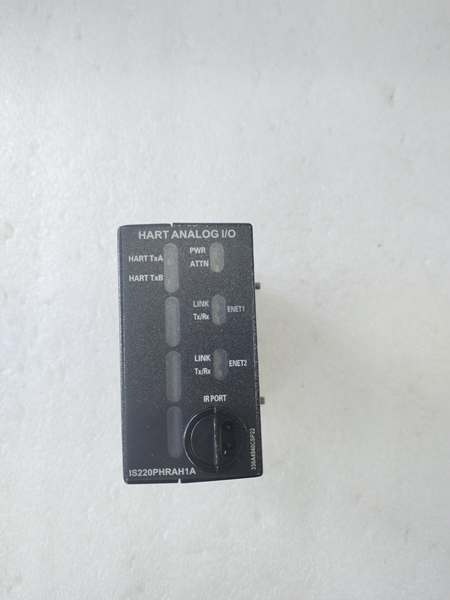
- LED Indicators: PWR, OK, FAULT, COMM (backplane communication), individual channel status LEDs
- Cooling: Forced air (requires Mark VIe backplane cooling)
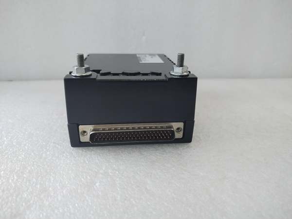
- Field Termination: Standard 50-pin terminal block (GE part number IS200THRH1A)
- Module Slot: Mark VIe I/O backplane (any slot in extension rack)
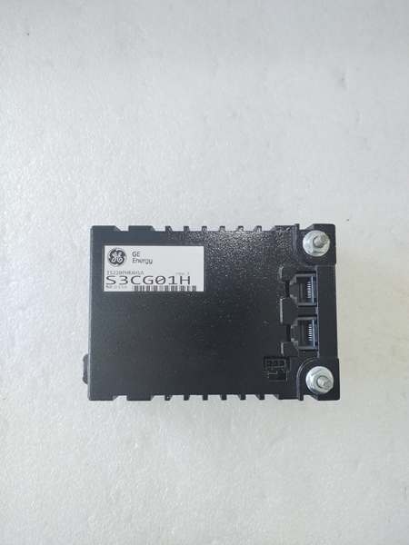
- Communication: Backplane via TCP/IP (embedded TC processor)
- Firmware Version: Compatible with Mark VIe v6.0 and later
- Calibration: Self-calibrating with external reference capability

GE IS220PHRAH1A
The Real-World Problem It Solves
Accurate temperature measurement is critical for turbine performance and protection. The IS220PHRAH1A delivers 16 channels of thermocouple input with automatic cold junction compensation and 0.1°C resolution, ensuring your control system sees true process temperatures without manual offset corrections.
Where you’ll typically find it:
- Gas turbine exhaust thermocouple arrays (multiple TCs for averaged temperature)
- Steam turbine inlet and exhaust temperature monitoring
- Bearing temperature measurement systems (multiple bearing locations)
Bottom line: It gives you high-density thermocouple measurement with CJC for precise temperature tracking.
Hardware Architecture & Under-the-Hood Logic
The IS220PHRAH1A is a dedicated thermocouple input module for Mark VIe turbine control racks. Each of the 16 channels has dedicated signal conditioning, cold junction compensation (CJC) circuit, ADC, and isolation amplifier. The module supports 8 thermocouple types (J, K, T, E, N, R, S, B), selected via software configuration per channel. Automatic cold junction compensation uses an onboard temperature sensor at the terminal block to compensate for ambient temperature effects. An embedded ARM processor manages channel configuration (thermocouple type, filter), data formatting, and backplane communication. Temperature data is transmitted to the main controller via backplane TCP/IP at 10 Hz update rate. The module includes self-calibration routine to compensate for ADC offset and gain drift. Firmware supports alarm thresholds (high temperature, low temperature, rate-of-change) configurable per channel.
Internal signal flow:
- Thermocouple signal arrives at terminal block (millivolt output from TC)
- Cold junction compensation sensor measures terminal block temperature
- Signal passes through protection circuits (TVS diodes for transient protection)
- Low-noise amplifier boosts millivolt signal to ADC range
- Anti-aliasing filter (low-pass) removes high-frequency noise
- ADC converts amplified signal to digital value
- CJC correction applied to digital value for ambient temperature
- Thermocouple type conversion table (NIST standard) applied
- Temperature value in engineering units (°C or °F) calculated
- Embedded processor formats temperature data into Ethernet packets
- Processor communicates with main controller via backplane TCP/IP
- Alarm logic evaluates temperature against thresholds
- Diagnostic data (CJC health, ADC health, open-circuit detection) generated

GE IS220PHRAH1A
Field Service Pitfalls: What Rookies Get Wrong
Mismatching thermocouple type causes massive measurement errorsThe module supports 8 thermocouple types, but configuration must match the physical sensor. I’ve seen technicians configure Type K for a Type J thermocouple, resulting in 50-100°C measurement errors.
- Field Rule: Verify the thermocouple type from the sensor nameplate or lead wire color code (Type J = black/white, Type K = yellow/red). Configure the correct TC type per channel in Mark VIe software. Test the channel by measuring a known temperature source (ice bath for 0°C, boiling water for 100°C). Document TC type per channel in your asset management system.
Improper thermocouple wiring creates offset errorsThermocouple polarity matters—reversing leads produces massive offset errors. I’ve seen technicians wire the red (negative) lead to the positive terminal, causing readings that are inverted or wildly inaccurate.
- Field Rule: Verify thermocouple lead polarity before wiring. Type K: Yellow is positive (+), Red is negative (-). Type J: Black is positive (+), White is negative (-). Always follow the thermocouple lead color code. Use a multimeter with microvolt mode to verify polarity by heating the junction—the output should be positive temperature. Document polarity convention in your wiring diagrams.
Long thermocouple runs without compensation create voltage dropsThermocouple signals are millivolt-level and susceptible to voltage drop over distance. I’ve seen technicians run 300 feet of extension wire without compensation, resulting in cold junction errors and temperature drift.
- Field Rule: Keep thermocouple extension wire runs under 100 meters (330 feet) for accuracy. Use thermocouple extension wire (not regular copper wire) with proper type matching (Type K extension wire for Type K thermocouples). If longer runs are unavoidable, use remote I/O with CJC at the measurement point. Document wire type and length in your installation records.
Using standard copper wire for extension causes measurement driftThermocouple extension wire must match the TC type. I’ve seen technicians use standard copper wire as extension, creating parasitic junctions that cause temperature drift and errors.
- Field Rule: Always use thermocouple extension wire of the same type as the thermocouple. Never splice thermocouple wire with standard copper wire—this creates unintended junctions that introduce errors. Use proper thermocouple junction blocks for connections. Verify extension wire type with a multimeter—resistance should be higher than copper wire due to thermocouple alloy composition.
Leaving unused channels unterminated causes random readingsUnused thermocouple channels float to ambient temperature or produce erratic readings due to noise pickup.
- Field Rule: Short unused thermocouple inputs at the terminal block (connect positive and negative terminals together). If the module supports disabling channels via software, disable unused channels. Never leave TC inputs open circuit—this can cause random readings that may trigger false alarms. Document unused channel status in your installation records.
Ignoring CJC health leads to calibration driftThe cold junction compensation sensor is critical for accuracy. I’ve seen technicians ignore CJC diagnostic warnings, resulting in gradual temperature drift up to 5°C over time.
- Field Rule: Monitor CJC health diagnostics in Mark VIe software. If CJC sensor drifts or fails, the module will report a fault. Perform annual calibration verification using a reference temperature source (ice bath at 0°C, dry block calibrator at 100°C). If CJC error exceeds ±1.0°C, replace the module. Document CJC verification in your calibration log.
Commercial Availability & Pricing Note
Please note: The listed price is for reference only and is not binding. Final pricing and terms are subject to negotiation based to current market conditions and availability.


