
Description
Hard-Numbers: Technical Specifications
- Number of Channels: 8 analog output channels
- Output Type: 4-20 mA, 0-20 mA, 0-10 VDC, ±10 VDC (configurable per channel)
- Resolution: 16-bit (up to ±0.015% full scale)
- Accuracy: ±0.1% full scale typical
- Update Rate: 100 Hz per channel
- Load Resistance: 0-600 Ω for current outputs, >1 kΩ for voltage outputs
- Output Range: 0-20 mA or 4-20 mA current, ±10 VDC voltage
- Programmable Scaling: Linear scaling with slope and offset configuration
- Isolation: 1500V RMS between output channels and backplane
- Module Power Draw: 2.5A @ 5VDC from backplane
- Backplane Current: 5V: 2.5A max
- Operating Temperature: -20°C to 70°C (-4°F to 158°F)
- Storage Temperature: -40°C to 85°C (-40°F to 185°F)
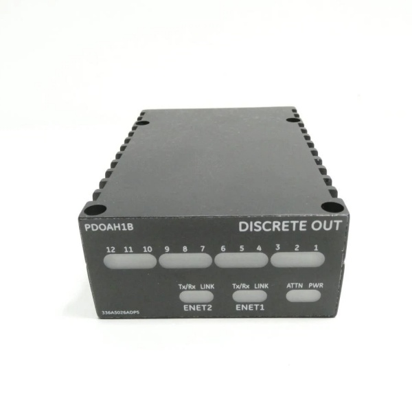
- LED Indicators: PWR, OK, FAULT, individual channel status LEDs
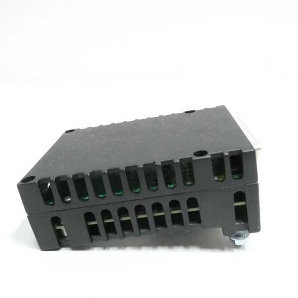
- Cooling: Forced air (requires Mark VIe backplane cooling)
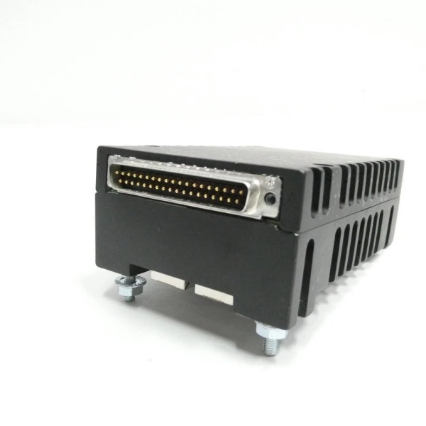
- Field Termination: Standard 36-pin terminal block (GE part number IS200EPSG1A)
- Module Slot: Mark VIe I/O backplane (any slot in expansion rack)
- Communication: Backplane via TCP/IP (embedded AO processor)
- Firmware Version: Compatible with Mark VIe v6.0 and later

GE IS220PDOAH1B
The Real-World Problem It Solves
Analog outputs are the final control element in turbine systems—driving servo valves, governor setpoints, and modulating valves. The IS220PDOAH1B delivers 8 channels of high-resolution analog output with programmable scaling, ensuring your valves receive precise commands from the main controller.
Where you’ll typically find it:
- Gas turbine fuel valve control loops
- Steam turbine governor valve positioning
- Compressor anti-surge valve control systems
Bottom line: It gives you multi-channel analog output with programmable scaling for precision valve control.
Hardware Architecture & Under-the-Hood Logic
The IS220PDOAH1B is a high-speed analog output module for Mark VIe turbine control racks. Each of the 8 channels has dedicated DAC (Digital-to-Analog Converter), output driver, and protection circuitry. The module supports both current (4-20 mA, 0-20 mA) and voltage (0-10 V, ±10 V) outputs, selected via software configuration for each channel. An embedded ARM processor manages channel configuration (scaling, range), data formatting, and backplane communication. Output data is received from the main controller via backplane TCP/IP at 100 Hz update rate. The module includes programmable linear scaling with slope and offset configuration to convert engineering units to output range. Output channels include open-circuit detection and short-circuit protection. The firmware supports both analog hold and fault response modes—on fault detection, outputs can be configured to hold last value or revert to a safe level.
Internal signal flow:
- Output command from main controller arrives via backplane TCP/IP
- Embedded processor parses command and applies scaling (slope/offset)
- Scaled value is sent to DAC (Digital-to-Analog Converter)
- DAC converts digital value to analog voltage or current
- Output driver amplifies signal to specified output range (4-20 mA or 0-10 V)
- Output signal passes through protection circuits (TVS diodes, current limiting)
- Feedback circuit monitors actual output for fault detection
- Open-circuit or short-circuit detection evaluates output integrity
- Diagnostic data is generated for monitoring
- Fault response logic executes if fault detected (hold last value or safe level)
- Front-panel LEDs reflect power status, communication status, and channel faults
GE IS220PDOAH1B
Field Service Pitfalls: What Rookies Get Wrong
Mismatching output range to load requirements causes incorrect operationThe module supports multiple output ranges. I’ve seen technicians set a channel for 4-20 mA current but wire a 1 kΩ voltage load, causing the module to fail to reach full-scale output.
- Field Rule: Configure the output type to match the load requirements. For valve positioners expecting 4-20 mA, configure current output. For PLC analog inputs expecting voltage, configure voltage output. Verify load resistance is within specified range (0-600 Ω for current, >1 kΩ for voltage). Test the output with a multimeter to confirm proper scaling.
Improper grounding causes ground loops and offset errorsAnalog outputs are sensitive to ground loops. I’ve seen valves drift off setpoint because the load ground was connected to a different reference than the module ground.
- Field Rule: Use single-point grounding for all loads connected to the IS220PDOAH1B. Tie all load grounds to the module ground reference at the terminal block. Never connect load grounds to earth ground at both ends—this creates ground loops. Measure ground potential difference between module ground and load ground—should be less than 1VAC.
Incorrect scaling values cause valve positioning errorsThe programmable scaling (slope and offset) converts engineering units to output range. I’ve seen technicians use default scaling values, causing valves to only move 50% of commanded stroke.
- Field Rule: Verify the correct scaling values for each output channel. Enter slope and offset based on the load’s input range (e.g., 0-100% command to 4-20 mA). Test output scaling by commanding 0%, 50%, and 100% to verify correct output levels. Document scaling values in your control system database.
Overloading current outputs causes saturation and heatingCurrent outputs are rated for 600 Ω maximum load resistance. I’ve seen technicians drive multiple loads in series totaling 1500 Ω, causing the module to saturate and overheat.
- Field Rule: Calculate total load resistance for current output loops. Keep total loop resistance below 600 Ω for 24VDC supply voltage. If higher resistance is unavoidable, increase loop voltage or use external loop power. Monitor module temperature during operation—if hot to touch, reduce load resistance or improve cooling.
Leaving channels unpowered during commissioning creates undefined behaviorOutputs with no load connected can float or oscillate. I’ve seen technicians leave channels configured but with open circuits, causing random outputs to adjacent channels.
- Field Rule: Tie unused current output channels to ground via 250 Ω resistor. Tie unused voltage output channels to ground via 1 kΩ resistor. Never leave analog outputs unterminated—this can cause oscillation and affect adjacent channels. Document unused channel termination status in your installation records.
Not configuring fault response leads to unsafe valve positionsThe module supports fault response modes (hold last value or revert to safe level). I’ve seen technicians leave fault response in “hold last value” mode for fuel valves, causing valves to stay at last commanded position on a fault.
- Field Rule: Configure fault response based on your safety analysis. For fuel valves, configure fault response to revert to safe level (typically 0% or fully closed). For governor valves, configure hold last value for transient response. Test fault response by simulating a loss of communication to the main controller. Document fault response mode per channel in your maintenance procedure.
Commercial Availability & Pricing Note
Please note: The listed price is for reference only and is not binding. Final pricing and terms are subject to negotiation based to current market conditions and availability.


