
Description
Hard-Numbers: Technical Specifications
- Protocol Support: IONet (100Mbps deterministic Ethernet)
- Port Count: 2× RJ45 Ethernet, 1× DC-37 field connector
- Data Rate: 100 Mbps full-duplex
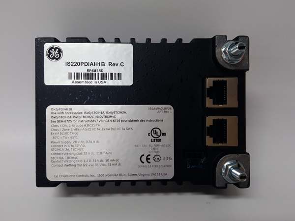
- Output Channels: 12 Form C relays, 3A @ 250VAC / 30VDC
- Isolation Rating: 1500 VAC field-to-backplane
- Power Requirements: 27.4–32.0 VDC, 4.2 W typical
- Operating Temperature: -30°C to +65°C
- Switching Time: <10 ms (relay operate/release)
- Hazardous Rating: Class I Div 2, Zone 2
- Dimensions: 133.4 × 38.1 × 82.6 mm
- Weight: 0.40 kg
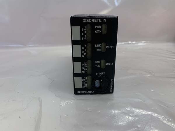
IS220PDIAH1A
The Real-World Problem It Solves
Control cabinets suffer from crowded wiring and unreliable field actuation when using generic output cards. Ground loops and EMI cause false trips in safety-critical turbine systems.
Where you’ll typically find it:
- Gas turbine emergency stop (ETS) solenoid control
- Fuel and steam valve actuation circuits
- Compressor anti-surge valve command outputs
Bottom line: delivers isolated, high-current switching with deterministic network control for heavy industrial loads.
Hardware Architecture & Under-the-Hood Logic
runs on a dedicated 32-bit processor with independent flash/RAM. Full galvanic isolation separates field outputs from backplane electronics.
- Controller commands arrive via dual redundant IONet Ethernet.
- On-board CPU validates commands and runs self-diagnostics.
- Output signals pass through 1500V isolation barriers.
- Relay coils energize with flyback diode protection for inductive loads.
- Output enable circuit holds relays de-energized until power-up self-tests pass.
- Channel status and fault data feed back to the controller.
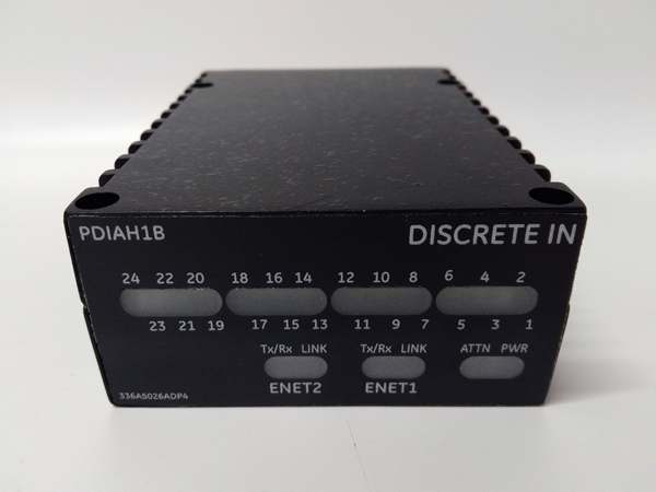
- Front LEDs indicate Power, Fault, TxRx, and Link status.
Field Service Pitfalls: What Rookies Get Wrong
Under-Sized Power WiringRookies use 24AWG wire for supply and load circuits. Voltage drop causes relay chatter and weak contact pressure.
- Field Rule: Use 20AWG (min) for 28VDC power; 18AWG for high-current outputs over 5m.
Missing Surge ProtectionUnsuppressed solenoids and motors induce voltage spikes that damage relay drivers.
- Quick Fix: Install 1N4007 flyback diodes (cathode to +28V) across every inductive load.
Hot-Swapping Without DisablePulling the module live creates backplane transients that lock the IONet node.
- Field Rule: Disable the node in Toolbox, wait 60 seconds, then remove the module.
Commercial Availability & Pricing Note
Please note: The listed price is for reference only and is not binding. Final pricing and terms are subject to negotiation based on current market conditions and availability.


