
Description
Hard-Numbers: Technical Specifications
- Processor: BPPx processor board for real-time I/O scanning, debounce logic, deterministic communication, and built-in self-diagnostics.
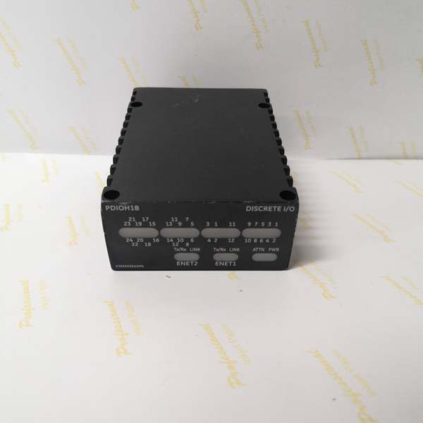
- Communication Protocol: Dual 10/100Base-TX Ethernet ports for redundant I/O network (IONet) integration with the Mark VIe controller.
- Supply Voltage: 24 V DC Nominal (Supports 18-32 V DC industrial range) .
- Power Consumption: ~12-15 W (Dependent on communication activity and relay coil energization) .
- Discrete Inputs (DI): 12 independent channels, optimized for dry contact sensing (voltage-free contacts) with integrated current limiting and noise filtering .
- Discrete Outputs (DO): 12 independent C-type (Form C) relay driver channels. Capable of sinking or sourcing 24 VDC at 1A per channel .
- Input Filter: Hardware-based 4 ms filter to eliminate contact bounce and high-frequency electrical noise .
- Voltage Suppression: 60 V RMS AC voltage suppression (at 50/60 Hz) to protect against inductive kickback and transient spikes .
- Input/Output Protection: Optical isolation (1500 VAC) between field-side circuits and control-side logic; overload and short-circuit protection on output drivers .
- Operating Temperature: -30°C to +65°C (Extended industrial rating for turbine compartments) .
- Humidity Tolerance: 5% to 95% non-condensing.
- Vibration Resistance: Engineered to meet IEC standards for rugged industrial environments.
- Protection: Industrial-grade conformal coating, channel-to-bus isolation, and IP20-rated enclosure. Certified for Class I Division 2 and ATEX Zone 2 hazardous locations .
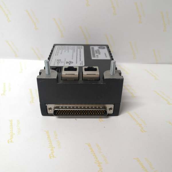
- Connectors: Dual RJ-45 Ethernet, one DC-37 pin connector for direct terminal board interface, one 3-pin power connector, and dedicated screw-terminal blocks for field wiring.
- Compatible Terminal Boards: TDBS (Simplex Discrete I/O) and TDBT (TMR Discrete I/O) .
- Incompatible Terminal Boards: Standard single-function boards like TBCI, TICI, or SRLY .
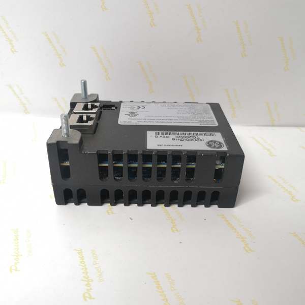
- Dimensions (Approx.): 15.875 cm x 10.795 cm x 4.65 cm (6.25″ x 4.25″ x 1.83″).
- Weight (Approx.): 0.5 kg (1.1 lbs).
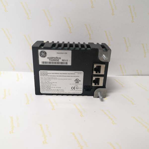
IS220PDIOH1B
The Real-World Problem It Solves
In turbine auxillary control cabinets, many subsystems require a 1:1 ratio of sensors to actuators. For example, a lube oil pump needs a start command (Output) and a run-status feedback contact (Input). Using a 24-input pack (PDIA) or a 12-output pack (PDOA) for such a subsystem leads to wasted I/O points and inefficient panel layouts.
The solves the problem of I/O imbalance and panel real estate. By integrating exactly 12 inputs and 12 outputs, it perfectly matches common auxiliary skids, valve yards, and motor control centers . Furthermore, it bridges the electrical gap between fragile controller logic and the harsh industrial world using 1500V optical isolation and hardware debouncing. This ensures that when an auxiliary motor starter closes its feedback contact, the Mark VIe controller reads a clean, noise-free signal without needing extra interposing relays .
Where you’ll typically find it:
- Mounted on TDBS (Simplex) or TDBT (Triple Modular Redundant) terminal boards in Mark VIe turbine control panels .
- Wired to auxiliary equipment clusters, such as the Lube Oil System (pump starts/status), Seal Gas System (valve commands/limits), and Ventilation/Fire Suppression controls .
- Deployed in both Gas and Steam turbine packages where a balanced mix of DI and DO is required without consuming multiple I/O rack slots .
Bottom line: It is the perfectly proportioned, noise-immune, all-in-one field interface that streamlines your turbine’s auxiliary controls into a single rugged package.
Hardware Architecture & Under-the-Hood Logic
Unlike standard single-function modules, the PDIOH1B houses a compact mixed-signal acquisition board tailored for symmetrical I/O, all governed by the standard BPPx processor .
- Mixed-Signal Conditioning: The 12 DI channels pass through precision current-limiting resistors and optical isolators for dry contact sensing. Simultaneously, the 12 DO channels are driven by robust C-type relay drivers capable of handling 1A loads, with integrated flyback diode protection to absorb inductive voltage spikes from external relays .
- Hardware Debouncing: A 4 ms hardware filter on the DI channels acts as the first line of defense against mechanical switch bounce and high-frequency EMI, physically preventing false triggering before the signal reaches the processor .
- Deterministic Communication: The onboard BPPx processor continuously scans the mixed input states and output statuses. It packages this data into Ethernet frames and transmits them to the Mark VIe controller via dual redundant IONet ports at configured frame rates (as fast as 10ms), ensuring minimal latency .
- Fault Management & Diagnostics: The processor continuously monitors its own health, communication link status, and power supply quality. If a critical fault is detected (e.g., loss of communication with the controller), it triggers hardware-level alarms. The front-panel LEDs provide at-a-glance diagnostics for system health, Ethernet activity, and individual channel energy .
IS220PDIOH1B
Field Service Pitfalls: What Rookies Get Wrong
The “Half-Deaf” Module (Wiring Mismatched Channels)
Because the PDIOH1B splits its 37-pin connector symmetrically (usually pins 1-12 for Inputs, 13-24 for Outputs), rookies often miscount during wiring, especially under time pressure during a startup.
- The Symptom: A technician wires a flow meter’s dry contact to what they think is Input Channel 1, but it’s actually Output Channel 1. The meter is constantly powered, the contact never registers, and the turbine trips on low lube oil flow.
- Field Rule: Measure, don’t guess.Use a multimeter to verify the exact pinout against the TDBS/TDBT terminal board documentation before energizing the loop. As veteran techs say: “On a PDIO, the first twelve are listeners, the next twelve are talkers. Know which one you’re poking.”
The Inductive Spike (Forgetting Flyback Protection on Outputs)
While the PDIOH1B has internal voltage suppression, rookies often assume it’s a magic shield and connect highly inductive loads (like large solenoid valves or mechanical relays) directly to the DO channels without external protection.
- The Symptom: The module works fine for a few weeks, then suddenly starts throwing random “Output Short Circuit” faults or completely dies on one bank of channels. Internally, the microscopic weld on the output driver has been blasted apart by an inductive voltage spike.
- Field Rule: Respect the 1A rating. If you are driving an inductive load, always add an external flyback diode across the load terminals (cathode to positive). The internal 60V RMS suppression is a last resort, not a design feature.
⚠️ Buyer Beware: The “Datasheet Scam”
If you are searching for this module online, you will find third-party reseller listings claiming the is a “24-Channel Isolated Input Module” or merging its specs with the PDIAor PDIIseries .
- The Reality: In the GE Mark VIe ecosystem,
PDIOstrictly stands for Process Discrete Input / Output assembly (12 DI / 12 DO) . Third-party brokers often use “Black Hat” SEO tactics, copy-pasting random specifications from other modules into their listings to game search engine algorithms . - The Fix: Never order critical spares based solely on a reseller’s webpage. Always cross-reference the 100-character GE part number (found on the physical label, e.g.,
336A4975ABPQ) with the official GE Mark VIe I/O pack compatibility charts (GEH-6721) before purchasing .
Commercial Availability & Pricing Note
Please note: The listed price is for reference only and is not binding. Final pricing and terms are subject to negotiation based on current market conditions and availability.


