
Description
System Architecture & Operational Principle
The is a distributed I/O pack in the Mark VIe hierarchy, living on a DIN rail (or mounted directly to a terminal board) rather than in a VME rack. It operates at Level 1/2, bridging the gap between the IONet (Ethernet) and the field devices.
Upstream, it connects to the controller (UCVE/UCVGH) via dual RJ45 ports (ENET1/ENET2), supporting redundant ring topologies. It handles its own IP addressing via DHCP or static assignment. Downstream, the physical interface is a DC-62 (37-pin D-sub style) connector that mates directly to a terminal board—either TDBS (Simplex) or TDBT (TMR).
Internally, it houses a dedicated processor that scans the 24 discrete inputs (dry contact sensing, 5-125V DC range) with a fixed 4ms hardware debounce filter. It drives 12 internal low-side switches to energize the coils on the attached terminal board’s relays (e.g., SRLY on TDBS, or TRLY on TDBT). This offloads the contact-debounce logic from the main controller, ensuring deterministic response for trip loops and status feedback without clogging the IONet bandwidth.
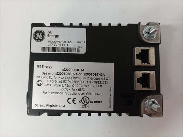
IS220PDIOH1A
Core Technical Specifications
- Input Channels: 24 (Dry Contact Sensing, Optically Isolated)
- Input Voltage Range: 5 V DC to 125 V DC (Hardware selected via Terminal Board)
- Input Filter: Fixed 4 ms Hardware Debounce (Non-configurable in basic modes)
- Output Channels: 12 (Form-C Relay Drivers / Low-Side Switches)
- Output Rating (Pack Side): Sinking 24 V DC @ ~1A per channel (Drives external relay coils)
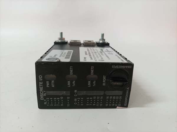
- Communication: 2x 10/100Base-TX (RJ45), Auto-Negotiate, Full/Half Duplex
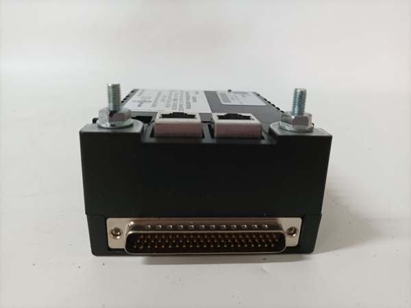
- Field Interface: 1x DC-62 (37-pin) Male Connector (To Terminal Board)
- Power Input: 27.4 – 28.0 V DC (3-pin Micro-Fit connector, Soft-Start capable)
- Isolation: 1500 Vrms (Field Inputs to Logic/Network)
- Diagnostics: Status, Boot, Fault, Act, Net A/B LEDs on faceplate
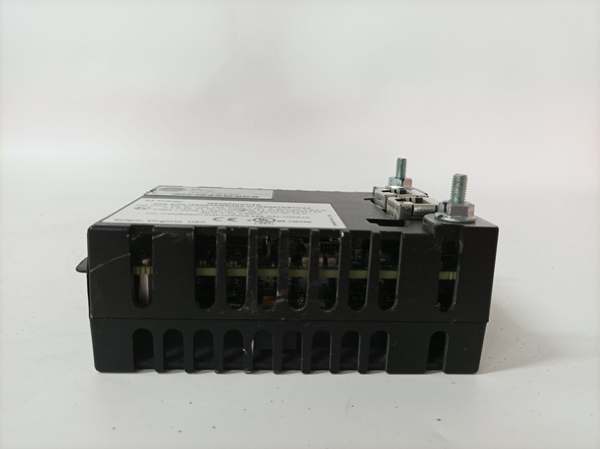
- Mounting: DIN Rail (TS-35) or Direct-to-Board (TDBS/TDBT)
- Environmental: 0°C to +60°C (Operational), Conformal Coated
Customer Value & Operational Benefits
Rack Footprint Reduction
The PDIO (Process Discrete I/O) concept kills the need for separate “Input Packs” and “Output Packs.” By combining 24 DI and 12 DO in one housing, the frees up roughly 50% of the I/O slots in a cabinet that would otherwise be eaten by PDIA+PDOA pairs. In a skid-mounted control panel or a crowded turbine aux rack, this saves real estate and cuts cable tray congestion.
Deterministic Local Processing
Unlike dumb remote I/O that forwards every edge-trigger to the controller, this pack handles the 4ms hardware debounce on-chip. It only reports a state change (“Contact Closed”) to the controller after the signal is stable. This prevents “flickering” limit switches or EMI spikes from the exciter bus from triggering false turbine trips or logging garbage data, directly improving Mean Time Between Spurious Trip (MTBST).
Simplified Spares Strategy
Since a single PDIO replaces two different spare types (PDIA and PDOA), your warehouse only needs to stock the . Whether a gas compressor station loses an input card or a lube oil pump output card, the same module works for both. This cuts inventory carrying costs and eliminates the “installed the wrong spare” downtime scenario at 3 AM.
Field Engineer’s Notes (From the Trenches)
The “Gotcha” on the H1A is the 4ms Hardware Filter—it’s a feature, until it isn’t. If you’re trying to count pulses from a turbine speed pickup or a high-speed flow meter (anything faster than 125 Hz / 8ms period), this module will choke and miss counts. It’s designed for contact sensing (valves, switches), not high-speed pulse trains—grab a PCCA or VVIB for that.
Second, watch the DC-62 Pin Retention. That 37-pin connector carries all 24 inputs and 12 drive signals. If you mount this on a DIN rail separate from the terminal board (using a flying cable), vibration will work that connector loose over 6-12 months. Use strain relief on the cable and periodically check the thumbscrew tightness.
Lastly, power it with a stiff 28.0 V DC source. The internal relay drivers drop some voltage; if your cabinet supply sags to 24V under load, the terminal board relays (especially 24V coils) might chatter or fail to pull in reliably during a cold start.
IS220PDIOH1A
Real-World Applications
- Auxiliary Lube Oil Skid (Simplex): Mounted on a TDBS terminal board. Inputs 1-10 read “Pump Running” aux contacts and “Filter Clogged” switches. Outputs 1-4 drive the starter coils for the lube oil pumps (via SRLY relays on the TDBS). The 4ms filter ignores contact bounce from the mechanical pressure switches.
- Steam Turbine Trip Logic (TMR): Three PDIO packs mounted on TDBT boards (R, S, T). They read “Overspeed Trip” dry contacts and “Vacuum Breaker Open” limits. Outputs drive the TRLY relay coils for Fuel Stop Valve closure. The TMR architecture ensures one loose field wire doesn’t cause a unit trip.
High-Frequency Troubleshooting FAQ
Q: ToolboxST shows “PDIO H1A – Hardware Mismatch” or “ID Fail” after replacement. What’s wrong?
A: The PDIO pack reads an ID Chip on the terminal board (TDBS/TDBT) to ensure the software configuration matches the hardware. If you swapped a TDBS (Simplex) board but kept the old “TMR” project file (or vice versa), it will fault. Verify the Terminal Board Type in the Controller Project (ToolboxST -> I/O Configuration) matches the physical board part number (e.g., IS200TDBSH2A vs IS200TDBTH2A).
Q: Input shows “TRUE” in ToolboxST but the field contact is Open (0V). Why?
A: You likely have Passive Sensing enabled or a voltage presence issue. The PDIO sources a small sensing current. If you’re using “Dry Contacts” but have 24V landed on the Return bus of the terminal board incorrectly, it backfeeds the input. Check the TDBS/TDBT jumper setup: for dry contacts, ensure no external voltage is on the common return unless configured for “Wet” mode.
A: Yes, the pack has Soft-Start on the 28V input, and the Ethernet ports handle link-down gracefully. However, do not pull the DC-62 connector while live if the outputs are energized—arcing the 28V coil drive pins can pit the connector pins. Use the software “I/O Disable” or “Simulate” mode before extracting, if possible.
Please note: The listed price is not the actual final price. It is for reference only and is subject to appropriate negotiation based on current market conditions, quantity, and availability.


