
Description
Hard-Numbers: Technical Specifications
- Processor: BPPx processor board for real-time I/O scanning, debounce logic, and deterministic communication.
- Communication Protocol: Dual 10/100Base-TX Ethernet ports for redundant I/O network integration with the Mark VIe controller.
- Supply Voltage: 24 V DC Nominal (Supports 18-30 V DC industrial range).
- Power Consumption: ~15 W (Dependent on active relay count and communication activity).
- Discrete Inputs (DI): 24 independent channels, optimized for dry contact sensing with integrated current limiting and noise filtering.
- Discrete Outputs (DO): 12 independent channels utilizing electromechanical relays (typically SPDT or SPST configurations).
- Contact Ratings (Outputs): Typically rated for 30V DC / 1A resistive or 250V AC / 2A inductive loads.
- Input/Output Protection: Optical isolation and galvanic isolation (1500 VAC) between the field-side I/O circuits and the control-side logic/communication circuits.
- Operating Temperature: -30°C to +65°C (Standard industrial range; capable of brief exposure to -40°C to +70°C extremes).
- Humidity Tolerance: 5% to 95% non-condensing.
- Vibration Resistance: Compliant with IEC 60068-2-6 standards for industrial control panels and turbine packages.
- Protection: Industrial-grade conformal coating and IP51-rated enclosure for dust and moisture resistance. Certified for Class I Division 2 and ATEX Zone 2 hazardous locations.
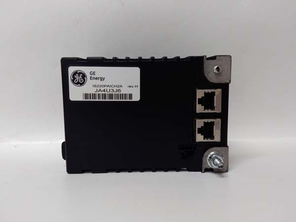
- Connectors: Dual RJ-45 Ethernet, one DC-37 pin connector for direct terminal board interface, and one 3-pin power connector.
- Dimensions (Approx.): 12.1 cm x 8.26 cm x 4.19 cm (4.78″ x 3.25″ x 1.65″).
- Weight (Approx.): 0.3 kg (0.66 lbs).

IS220PAICH2A
The Real-World Problem It Solves
In a running gas or steam turbine, not everything is controlled by gradual analog signals; many critical operations are binary (On/Off, Open/Closed). The solves the fundamental problem of reliably interfacing the Mark VIe controller with the chaotic, electrically noisy world of field contact wiring.
It acts as a bulkhead, electrically isolating 24 sensitive digital inputs and 12 robust relay outputs from the controller’s fragile logic circuits. Because it features optical isolation and hardware-level debouncing, it eliminates the “ghost switching” caused by electrical noise, ensuring that a spurious voltage spike doesn’t accidentally trip a turbine or, worse, prevent a critical emergency stop from engaging. Without this module, the turbine would lose its ability to reliably detect limit switches, emergency stops, or control heavy-duty solenoids, leading to severe safety risks and operational instability.
Where you’ll typically find it:
- Mounted directly onto compatible discrete I/O terminal boards (such as the TDBS or TDBT variants) within the turbine control cabinet using a DC-37 pin connector.
- Wired to field devices like start/stop pushbuttons, lube oil pump run statuses, ventilation fan alarms, and fuel valve limit switches.
- Integrated into Triple Modular Redundant (TMR) or Dual Modular Redundant (DMR) architectures where its software-implemented fault tolerance (SIFT) ensures that a single point of field wiring failure won’t compromise the turbine’s safety.
Bottom line: It is the rugged, isolated gateway that ensures the Mark VIe brain accurately hears the “yes/no” status of the physical plant.
Hardware Architecture & Under-the-Hood Logic
The is engineered as a high-reliability, fault-tolerant digital I/O node. Its internal architecture is designed to prevent contact bounce and electrical noise from reaching the controller.
- Input Signal Conditioning: The 24 discrete inputs pass through precision current-limiting resistors and optical isolators. A small “wetting current” is sourced to keep contact surfaces clean. The onboard processor applies digital debounce algorithms to filter out mechanical chatter from switches.
- Output Drive Stage: The 12 relay outputs are driven by the BPPx processor via high-current buffer transistors. The processor continuously monitors the state of the relay coils and compares them against the commanded state.
- Deterministic Communication: The processor packages the sanitized digital input states into Ethernet frames and transmits them to the Mark VIe controller at the configured frame rate (as fast as 10ms). Simultaneously, it listens for output state commands from the controller.
- Fault Management: If the processor loses communication with the controller or detects an internal hardware fault (like a stuck relay contact), it can be configured to force all outputs to a predefined safe state (energized or de-energized) to protect the turbine.

IS220PAICH2A
Field Service Pitfalls: What Rookies Get Wrong
The “Phantom Closure” (Improper Wetting Current)
Rookies often treat dry contacts as simple open/closed switches, ignoring the physics of oxidation. Over time, inactive contacts develop a thin layer of oxidation that acts as an insulator.
- The Symptom: The Mark VIe system randomly alarms, claiming a limit switch has tripped or a pump has stopped, even when the physical device hasn’t moved. Wiggling the wires makes the alarm come and go.
- Field Rule: Dry contacts require a minimum “wetting current” (typically 5-10mA) to blast through oxidation and ensure a solid electrical connection. Verify that the ‘s internal wetting current is sufficient for the connected contact. If the field device uses long, small-gauge wires, the voltage drop might be too high. Measure the actual current flowing through the closed contact; if it’s near zero, you may need to add an external pull-up resistor to boost the wetting current.
The “Stuck Relay” (Inductive Kickback)
When driving heavy loads like solenoids or large contractor coils, rookies often forget that inductors store massive amounts of energy in their magnetic fields.
- The Symptom: A relay channel on the PD10H1B works fine for a few weeks, then permanently welds shut (stuck “ON”) or fails open (stuck “OFF”). The module may also spontaneously reset or throw communication errors when a specific output activates.
- Field Rule: The collapse of a magnetic field in an inductive load creates a massive voltage spike (kickback) that can jump across the relay contacts, welding them together, or couple into the module’s power supply, causing a brownout. Always install an external flyback diode (for DC loads) or an RC snubber circuit (for AC loads) directly across the inductive device terminals. Never rely solely on the module’s internal protection for heavy inductive loads.
Ground Loop Ghosting
Rookies often assume “ground is ground” and daisy-chain the 0V/Common terminals of multiple field power supplies to the .
- The Symptom: Activating one input channel (e.g., pressing a pushbutton) causes other, completely unrelated input channels to suddenly read as “active” in the controller.
- Field Rule: In large plants, different pieces of equipment can have grounds at slightly different potentials (sometimes several volts apart). Connecting these disparate grounds together at the I/O module creates a “ground loop,” causing stray currents to flow through the common return path, falsely triggering inputs. Whenever possible, use the ‘s optically isolated inputs and dedicate a separate, isolated power supply for your digital inputs, ensuring all field grounds tied to the module are truly at the same potential.
Commercial Availability & Pricing Note
Please note: The listed price is for reference only and is not binding. Final pricing and terms are subject to negotiation based on current market conditions and availability.


