

Description
Hard-Numbers: Technical Specifications
- Processor: BPPB processor board combined with dedicated analog output hardware for real-time signal processing and diagnostics.
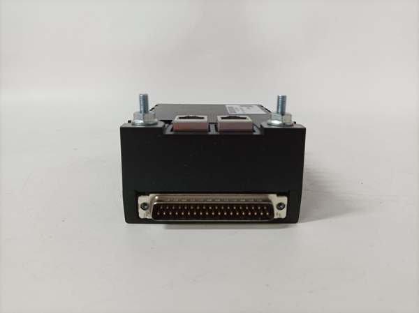
- Communication Protocol: Dual 10/100Base-TX Ethernet ports for deterministic communication with the Mark VIe controller and redundant networking.
- Supply Voltage: 27.4 V DC Nominal (Internal regulation handles typical 24V DC industrial supplies).
- Power Consumption: ~10–15 W (Dependent on output channel load and communication activity).
- Analog Outputs (AO): 8 independent simplex channels, 0-20 mA range (suitable for standard 4-20mA industrial loops).
- Output Precision & Drive: ±0.5% accuracy over the full operating temperature range. Features an 18V compliance voltage and supports up to 900Ω maximum load per channel.
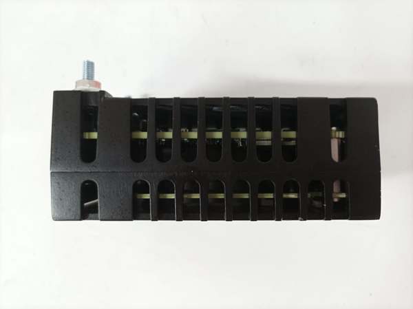
- Current Feedback & Diagnostics: Equipped with a 16-bit ADC and a precision 50Ω sensing resistor on the terminal board to continuously monitor actual loop current and compare it against the commanded value.
- Output Protection: Each channel includes a mechanical normally-open “suicide” relay for hardware-level fault isolation and fail-safe positioning.
- Operating Temperature: -30°C to +65°C (Standard industrial range; capable of brief exposure to -40°C to +70°C extremes).
- Humidity Tolerance: 5% to 95% non-condensing.
- Vibration Resistance: Compliant with IEC 60068-2-6 standards for industrial control panels and turbine packages.
- Protection: Industrial-grade conformal coating and IP51-rated enclosure for dust and moisture resistance. Certified for Class I Division 2 and ATEX Zone 2 hazardous locations.
- Isolation: Reinforced galvanic isolation (2500 Vrms) between field-side output circuits and the control-side logic/communication circuits.
- Connectors: Dual RJ-45 Ethernet, one DC-37 pin connector for direct terminal board interface, and one 3-pin power connector.
- Dimensions (Approx.): 12.1 cm x 8.26 cm x 4.19 cm (4.78″ x 3.25″ x 1.65″).
- Weight (Approx.): 0.3 kg (0.66 lbs).

IS220PAOCH1A
The Real-World Problem It Solves
In a running gas or steam turbine, the control system constantly needs to adjust physical parameters—like fuel flow, inlet guide vane angles, or steam admission valve positions. The solves the fundamental problem of translating the Mark VIe controller’s digital decisions into highly accurate, interference-free analog currents that drive field actuators.
Because it features continuous current feedback (measuring exactly how much current is actuallyflowing in the loop versus what was commanded), it eliminates the “blind spot” found in cheaper output modules. If a wire breaks or a valve solenoid fails, the PAOCH1A detects the discrepancy instantly and alerts the control system. Without this module, the turbine would lose its ability to smoothly modulate physical processes, leading to inefficient operation or forced shutdowns.
Where you’ll typically find it:
- Mounted directly onto compatible analog output terminal boards (such as the TBAOH1C or STAOH1A/H2A) within the turbine control cabinet using a DC-37 pin connector.
- Providing the critical 4-20mA control signals to liquid fuel bypass valves, gas fuel control valves, compressor anti-surge valves, and generator excitation systems.
- Integrated into Triple Modular Redundant (TMR) architectures where its software-implemented fault tolerance (SIFT) ensures that a single point of failure won’t trip the entire turbine.
Bottom line: It is the reliable muscular interface that turns the Mark VIe brain’s digital commands into smooth, precise physical actions in the turbine system.
Hardware Architecture & Under-the-Hood Logic
The is engineered as a high-reliability, fault-tolerant control node. Its internal architecture is built to prevent silent failures and ensure output integrity.
- Command Processing: The onboard BPPB processor receives digital setpoints from the Mark VIe controller via dual Ethernet links. It processes these commands, applying linearization and scaling as configured in the ToolboxST software.
- Precision Conversion: The processor sends the scaled digital values to high-resolution 16-bit Digital-to-Analog Converters (DACs). An external transistor amplifier stage then regulates the actual loop current to match the DAC’s voltage output precisely.
- Closed-Loop Verification: Unlike “fire-and-forget” output cards, the PAOCH1A actively monitors its own performance. A 16-bit Analog-to-Digital Converter (ADC) reads the voltage drop across a precision 50Ω shunt resistor on the terminal board, calculating the exact current flowing through the field loop.
- Fault Management: The processor continuously compares the commanded current with the measured feedback current. If the difference exceeds a predefined threshold (indicating an open circuit, short circuit, or hardware fault), the processor can trigger the channel’s dedicated mechanical relay to disconnect the output, preventing the field actuator from behaving erratically.
IS220PAOCH1A
Field Service Pitfalls: What Rookies Get Wrong
The “Mystery of the Drooping Valve” (Improper Load Calculation)
Rookies often assume that if a device is rated for 0-20mA, it will work with any 4-20mA valve or transmitter. They overlook the critical relationship between cable distance, loop power, and load resistance.
- The Symptom: The turbine is running, but a critical control valve cannot reach its fully open position, or the analog signal becomes unstable under heavy electrical loads. The PAOCH1A may sporadically throw “Compliance Voltage Exceeded” or “Feedback Mismatch” alarms.
- Field Rule: Before commissioning, calculate the total loop resistance (field device impedance + cable resistance). The PAOCH1A has an 18V compliance voltage. Using Ohm’s Law (Voltage = Current × Resistance), ensure that 20mA × Total Loop Resistance is less than 18V. For long cable runs, voltage drop can be significant. If the loop resistance is too high, you may need to install a separate loop isolator/power supply closer to the field device.
Chasing Ghosts (Ignoring the 50Ω Shunt Resistor)
When the PAOCH1A reports a “Feedback Mismatch” alarm, rookies often immediately condemn the I/O pack itself, assuming the DAC or ADC has failed.
- The Symptom: The commanded output is 12mA, but the module alarms because it reads 0mA or a wildly different value, even though the valve appears to be holding position.
- Field Rule: Remember that the measures its output current through a . Before swapping the expensive I/O pack, inspect the terminal board (e.g., TBAOH1C). Check for corroded pins in the DC-37 connector, loose terminations, or a failed shunt resistor. A poor connection at the terminal board is a very common cause of false current feedback alarms.
The “Phantom Trip” (Misunderstanding Suicide Relay Logic)
The features mechanical “suicide” relays that physically disconnect the output during a detected fault or a processor watchdog timeout. Rookies often disable these relays in the software because they find them annoying during testing.
- The Symptom: During a minor process upset or a brief network hiccup, the turbine experiences a massive, uncontrolled surge because a fuel control valve failed in a dangerous position (wide open) instead of snapping shut.
- Field Rule: Never disable the hardware-level fault protection (suicide relays) on analog output modules controlling critical turbines. The “nuisance trips” rookies try to avoid are actually the module doing its job—detecting a potentially catastrophic control anomaly and forcing the attached actuator into a safe, predetermined state. Ensure your ToolboxST configuration has the suicide relay logic properly mapped to your turbine’s specific safety requirements.
Commercial Availability & Pricing Note
Please note: The listed price is for reference only and is not binding. Final pricing and terms are subject to negotiation based on current market conditions and availability.


