
Description
硬性数据:技术规格
- 处理器: 高级BPPx(板级支持包处理器),集成高分辨率ADCs/DACs,用于实时信号处理。
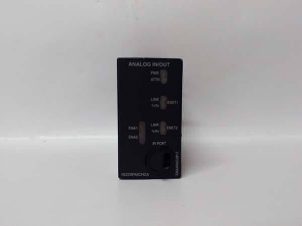
- 通信协议: 两个10/100Base-TX以太网端口,用于与Mark VIe控制器背板进行确定性通信。
- 供电电压: 24 V DC 标称值(宽工作范围 18–36 V DC,以应对严重的工业电源波动)。
- 功耗: 约10-20瓦(取决于激活通道数量和通信负载)。
- 模拟输入 (AI): 共有10个通道。通道1-8可以配置为±5 V、±10 V或4-20 mA。通道9-10固定为1 mA或4-20 mA电流输入。
- 模拟输出 (AO): 2 通道(标准0-20 mA,第一个输出有硬件支持0-200 mA用于重型执行器)。
- 信号调理:内置可编程滤波、开路检测、过范围检测和冷端补偿,以获得精确的传感器读数。
- 工作温度: -40°C 到 +85°C(标准控制柜范围;某些型号支持 -40°C 到 +60°C)。
- 湿度耐受性: 5%到95%不冷凝。
- 抗振动性: 符合IEC 60068-2-6和MIL-STD-810标准,适用于工业和旋转机械应用。
- 保护: 工业级的聚氨酯或硅胶 conformal coating,可提供卓越的防潮、防尘和防化学污染保护。
- 隔离: 在现场输入/输出和控制侧逻辑/通信电路之间加强电气隔离(通常为1500V交流电或更高),以防止接地回路和电涌。
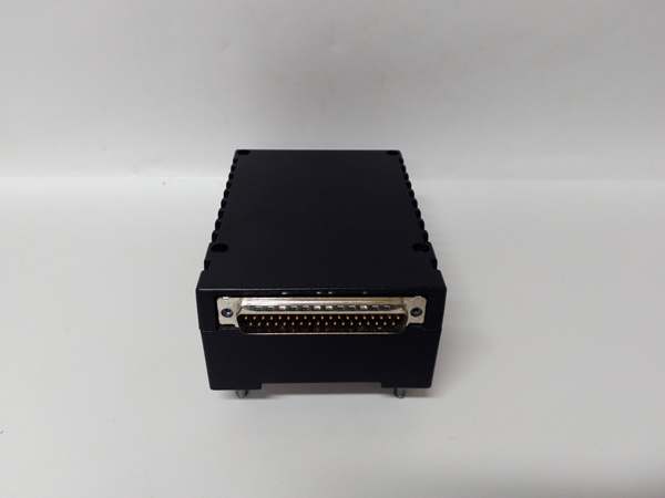
- 连接器: 双RJ-45以太网,一个用于端子板接口的DC-37针连接器,以及一个3针电源连接器。
- 尺寸(约):紧凑型DIN导轨或面板安装外壳(典型尺寸约为120毫米 x 80毫米 x 40毫米)。
- 重量(约): 0.2–0.5 公斤。
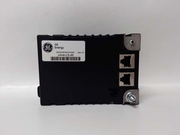
IS220PAICH2A
它解决的实际问题
在复杂的工业涡轮机或发电设施中,数百个模拟信号——如温度、压力、流量和阀门位置——必须被持续监控和控制。解决的核心问题是准确地将高密度的模拟信号数字化并提供闭合回路控制输出,同时将它们与工厂的嘈杂电气环境隔离。它确保Mark VIe控制器接收干净、精确的数据,以进行瞬间控制决策。”B”修订版通常会采用增强的组件,以提供更好的抗噪声性能、更快的采样率或在高温环境中的更长使用寿命。没有这个模块,控制系统将失去对涡轮机物理过程的控制。
Where you’ll typically find it:
- Mounted on terminal boards (such as TDBS or TBCI) within the turbine control cabinet, main PLC rack, or distributed I/O stations in the field.
- Interfacing directly with 4-20mA current loops from pressure transmitters, 0-10V signals from LVDTs (Linear Variable Differential Transformers), or thermocouple/millivolt inputs from temperature sensors.
- Sending analog control signals to hydraulic proportional valves, governor actuators, or VFDs to modulate turbine speed, load, or auxiliary system parameters.
Bottom line: It is the crucial analog nerve ending that allows the Mark VIe digital brain to accurately perceive and smoothly control the continuous physical variables of the turbine system.
Hardware Architecture & Under-the-Hood Logic
The PAICH2B is designed as a ruggedized, high-precision data acquisition and control node. Its internal architecture is optimized for deterministic signal processing and seamless integration into the Mark VIe Ethernet I/O network.
- Signal Acquisition & Conditioning: Incoming analog signals from the field pass through precision instrumentation amplifiers and anti-aliasing filters. The module performs necessary linearization and scaling (e.g., converting millivolts from a thermocouple to degrees Celsius) before presenting the data to the onboard microcontroller.
- High-Resolution Conversion: The heart of the module consists of high-resolution Analog-to-Digital Converters (ADCs) for inputs and Digital-to-Analog Converters (DACs) for outputs. These ensure minimal quantization error and high fidelity in signal representation.
- Microcontroller Processing: The onboard BPPx processor manages the sampling rates, executes calibration routines, performs self-diagnostics, and packages the digitized data into Ethernet frames for transmission to the main Mark VIe controller. It also receives digital setpoints from the controller and converts them into precise analog output voltages or currents.
- Fault Detection & Isolation: The module continuously monitors its own health, power supply quality, and communication link status. If a critical fault is detected (e.g., open sensor loop, short circuit, or loss of communication), it can trigger hardware-level alarms or fail-safe states to protect the turbine and connected equipment.
IS220PAICH2A
Field Service Pitfalls: What Rookies Get Wrong
The “Ghost Reading” Caused by Improper Grounding/Shielding
Rookies often focus solely on the module itself when troubleshooting erratic analog readings, overlooking the fundamental importance of proper grounding and shielding in the field wiring. They might swap the PAICH2B, only to find the mysterious fluctuations persist.
- The Symptom: Analog input values jitter or drift randomly, especially when nearby heavy machinery (like large motors or pumps) turns on or off. The readings may show sudden spikes or drops that don’t correspond to actual physical changes in the process.
- Field Rule: Before replacing the I/O pack, meticulously check the shielding and grounding of the field cables. Ensure that the shield is properly terminated (often at one end, typically the source) and that there are no ground loops. Use a multimeter to verify that the analog common (return) has a solid, low-impedance connection to the system ground. Clean, stable power and signal grounds are paramount for accurate analog measurements.
Ignoring the Jumper/Switch Settings
The PAICH2B often has hardware jumpers or DIP switches that configure the input/output ranges (e.g., 4-20mA vs. 0-10V) or termination resistors for specific sensor types (like RTDs or thermocouples). Rookies might install a new module with the factory default jumper settings, assuming it will automatically adapt to the existing field wiring.
- The Symptom: The module powers up fine, but the analog readings are completely out of scale (e.g., a 4-20mA signal reads as 0-10V, giving wildly incorrect process values), or the module reports an “Open Circuit” fault even though the sensor is connected.
- Field Rule: Always compare the jumper/DIP switch settings of the old (faulty) module with the new replacement beforeinstalling it. If the old module’s settings are unknown, consult the turbine’s electrical drawings or the Mark VIe I/O configuration documentation to ensure the hardware matches the software expectations. A quick photo of the old module’s jumpers can save hours of troubleshooting.
Overlooking the Need for Loop Calibration/Trimming
While the PAICH2B is a high-precision instrument, real-world components can drift over time, or the module itself might have been replaced with one that has slightly different internal voltage references. Rookies often assume that a new module is perfectly calibrated for their specific loop and skip the crucial step of loop calibration.
- The Symptom: The turbine control system reacts incorrectly to process changes because the analog input values, while stable, are offset from the true physical value (e.g., a pressure transmitter reads 50% when the actual pressure is 60%).
- Field Rule: Whenever a PAICH2B module is replaced, or if significant maintenance has been performed on the connected analog instruments, always perform a full loop calibration. Inject known simulated signals (e.g., 4mA, 12mA, 20mA) at the module terminals and verify that the Mark VIe controller reads them accurately. Conversely, force analog outputs and verify the field device’s response. Use the controller’s trim/gain functions to align the digital values with the physical reality of the plant.
Commercial Availability & Pricing Note
Please note: The listed price is for reference only and is not binding. Final pricing and terms are subject to negotiation based on current market conditions and availability.


