
Description
Hard-Numbers: Technical Specifications
- Processor: 32-bit Embedded Microcontroller (Optimized for high-speed analog servo loop control)
- Communication Protocol: Non-CANbus (Relies on Analog Command Inputs, Discrete I/O, and Feedback Signals)
- Supply Voltage: 24 V DC Nominal (Operating range 18–32 V DC to handle nacelle voltage fluctuations)
- Power Consumption: ~20–50 W (Dependent on pitch motor load and actuator type)
- Torque Rating: Calibrated for 30 Nm nominal pitch drive control (fully compatible with 40 Nm and select 20 Nm variants)
- Signal Conditioning: High-precision differential analog channels for position feedback, current sensing, and superior noise rejection
- Operating Temperature: -30°C to +65°C (Engineered for extreme nacelle and hub environments)
- Humidity Tolerance: 5% to 95% non-condensing
- Vibration Resistance: Compliant with IEC 60068-2-6 standards for rotating hub applications
- Protection: Conformal coating for humidity, salt mist, and vibration resistance
- Isolation: Galvanic isolation on critical I/O paths to prevent ground loops and protect against electrical transients
- Dimensions (Approx.): 200 mm × 160 mm × 50 mm (Compact PCB form factor)
- Weight (Approx.): 0.8–1.2 kg
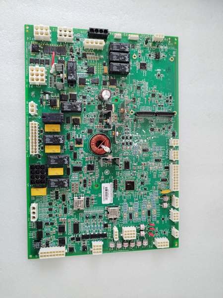
IS215WEPAH2BA
The Real-World Problem It Solves
As wind turbine technology has evolved, many older or internationally deployed Mark VIe turbines were originally commissioned with analog-controlled pitch drives rather than modern digital CANbus networks. The solves the problem of modernizing and maintaining these legacy fleets. By utilizing robust analog command and feedback loops instead of serial communication, this module ensures that turbines with traditional (non-CANbus) pitch drives continue to operate with pinpoint accuracy. It seamlessly integrates into the Mark VIe architecture, translating the main controller’s digital setpoints into precise analog voltage signals that drive the pitch motor, all while providing the necessary safety redundancy to feather the blades during emergencies.
Where you’ll typically find it:
- Mounted on the pitch drive assembly or inside the hub’s local control box of legacy GE Mark VIe wind turbines.
- Connected directly to non-CANbus pitch motor drives (such as selected 30/40 Nm units) via shielded twisted-pair analog cables.
- Interfacing with absolute encoders or resolvers to provide real-time blade position feedback to both the local pitch drive and the main nacelle controller.
Bottom line: It acts as the crucial analog bridge between the Mark VIe’s digital brain and the brute-force analog machinery of the pitch system, ensuring that older turbine platforms remain reliable, efficient, and safe.
Hardware Architecture & Under-the-Hood Logic
Unlike its CANbus-capable siblings, the WEPAH2BA is built around a high-speed analog servo architecture. It is designed to thrive in environments where digital communication might be prone to interference, offering a direct, hardwired control path that many field technicians find easier to troubleshoot using a multimeter.
- Analog Command Processing: Receives analog DC voltage signals (e.g., +/- 10V) from the main Mark VIe controller, which represent the target blade angle.
- Closed-Loop Servo Control: Continuously compares the command signal against the actual blade position (received from an analog encoder or resolver). The onboard microcontroller executes a high-speed PID loop, adjusting the output current to the pitch motor to eliminate any positional error.
- Drive Monitoring & Protection: Monitors analog feedback for motor current and temperature. If an over-current condition or a mismatch between command and actual position is detected, the module triggers a hardware-level fault and initiates an emergency feathering sequence using hardwired safety circuits.
- Status Reporting: Converts local diagnostic data (drive status, fault conditions) into discrete (on/off) signals and analog telemetry, sending them back to the main controller for SCADA logging and alarm generation.
IS215WEPAH2BA
Field Service Pitfalls: What Rookies Get Wrong
The “Phantom Voltage” Calibration Trap
Rookies often assume that if the turbine is off and the control system is powered down, the analog command lines to the WEPA module will be at 0 Volts. However, induced phantom voltages from nearby contactors or improperly drained capacitors can leave a residual voltage on the analog lines.
- The Symptom: After reinstalling the module and powering up, the blade violently snaps to an unexpected position because the controller “saw” a false command voltage during the initialization sequence.
- Field Rule: Always use a multimeter to verify that all analog input/output terminals are reading true 0.00V before reconnecting a replacement WEPA board. If you see stray voltage (even 0.5V), trace it back to the source and bleed it off before powering up.
Ignoring Shield Drain Wire Grounding
In a non-CANbus system, the analog signals are highly susceptible to Electromagnetic Interference (EMI) from the pitch motor’s power cables. Rookies often focus on getting the +24V and signal wires connected but pay little attention to how the shield drain wire is terminated at the terminal block.
- The Symptom: The turbine throws intermittent “Pitch Position Deviation” faults whenever the pitch motor ramps up to high speed, causing unnecessary wear on the gears.
- Field Rule: Ensure the shield drain wire is properly grounded at the WEPA terminal block (and ONLY at the WEPA end, to avoid ground loops). A poor shield connection is just as bad as no shield at all.
Mismatched Analog Scaling (The 20mA vs 10V Mix-up)
Different pitch drive manufacturers (or even different generations of the same drive) use varying analog standards—some use 0-20mA current loops, while others use +/- 10V voltage signals for position commands and feedback. Rookies often swap a failed drive or WEPA module without verifying the analog scaling jumper settings on the board.
- The Symptom: The blade moves in the opposite direction of the command, or the pitch rate is drastically slower/faster than expected, leading to an immediate software trip.
- Field Rule: Before buttoning up the hub, always pull the schematic and visually confirm that the jumper configurations (or DIP switch settings) on the WEPA board match the analog standard of the connected pitch drive.
Commercial Availability & Pricing Note
Please note: The listed price is for reference only and is not binding. Final pricing and terms are subject to negotiation based on current market conditions and availability.


