
Description
Hard-Numbers: Technical Specifications
- Protocol Support: EGD (Ethernet Global Data), SRTP, Modbus TCP, Genius
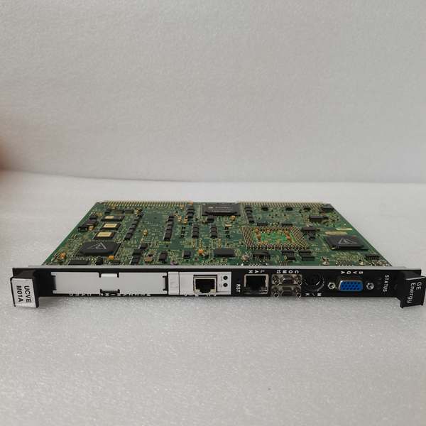
- Port Count: 2 x Fiber Optic (Tx/Rx), 1 x RS-232 Debug
- Data Rate: 200 Mbps (Proprietary Fiber), 115.2 kbps (Serial)
- Operating Temperature: -30°C to +65°C (-22°F to 149°F)
- Isolation Rating: 1500 V AC (Fiber Port to Backplane)
- Power Draw: 5 V @ 1.2 A, 12 V @ 0.3 A (Typical)
- Bus Interface: VME64x (Slave)
- Indicators: 2 x Link Status LEDs, 1 x Error LED
- Dimensions: 160 mm x 100 mm (6U VME)
- Weight: 0.4 kg (0.88 lbs)
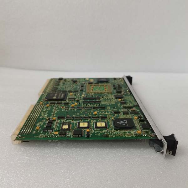
IS215UCVEM01A
The Real-World Problem It Solves
Ground loops and electrical noise are the silent killers of turbine control systems. This module creates a completely isolated, high-speed fiber link between your controller and remote I/O, keeping your data clean and your hardware safe from surges.
Where you’ll typically find it:
- Mounted in the main Mark VIe VME rack, talking to remote TBCI/TBUI I/O packs.
- Connecting control cabinets across a generator terminal box in a noisy switchyard.
- Serving as the primary data highway in a Mark VIe Safety Instrumented System (SIS).
Bottom line: It moves critical control data across the plant without picking up electromagnetic interference (EMI).
Hardware Architecture & Under-the-Hood Logic
This board acts as a protocol translator and data ferry. It doesn’t run the main turbine logic, but it ensures the controller’s commands reach the I/O and sensors on time. It handles the heavy lifting of packet assembly so the main CPU doesn’t choke on communication overhead.
- VME Bus Interface: Listens for data requests from the main controller (UCVE) via the VME backplane.
- Packet Processing: Grabs I/O status updates and packages them into high-speed frames.
- Fiber Transmission: Shoots the data through the fiber optic transceiver to the remote I/O drops.
- Status Monitoring: Continuously checks the health of the fiber links and reports errors back to the controller.
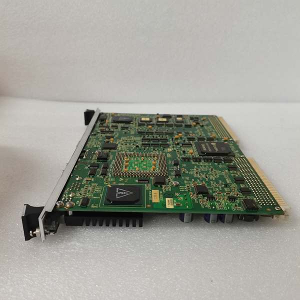
IS215UCVEM01A
Field Service Pitfalls: What Rookies Get Wrong
The “Dirty” Fiber Connection
New guys love to plug in a fiber cable without inspecting it. A single fingerprint or a speck of dust on the fiber end can kill the optical link. The Link LEDs will stay dark, and the system will throw a “Loss of Communication” fault.
- Field Rule: Never look at the bare fiber end. Always inspect it with a fiber scope and use proper wipes with isopropyl alcohol before mating.
Ignoring the DIP Switches
The VCMI relies on hardware-addressable node IDs to route data correctly. If you swap a failed unit and forget to set the DIP switches to match the old unit, the controller won’t recognize it.
- Quick Fix: Photograph the DIP switch positions on the old, failed board before pulling it out. Replicate the exact binary code on the replacement.
Cabling Strain Relief
Technicians often leave the fiber optic cables dangling or tightly looped right at the connector. Over time, vibration from the turbine causes micro-cracks in the fiber, leading to intermittent data loss.
- Field Rule: Use the provided strain relief clamps. Leave a slight service loop (about 2 inches) in the fiber to absorb any mechanical vibration.
Commercial Availability & Pricing Note
Please note: The listed price is for reference only and is not binding. Final pricing and terms are subject to negotiation based on current market conditions and availability.


