
Description
Hard-Numbers: Technical Specifications
- Controller Type: Embedded PLC (Mark VIe Compact)
- Processor: Marvell PXA166 @ 800 MHz (ARM-based)
- Memory: 512 MB DDR RAM, 2 GB Flash storage
- Program Memory: 128 KB user logic storage
- Digital Inputs: 16 channels (24VDC sinking/sourcing)
- Digital Outputs: 8 channels (24VDC relay outputs)
- Analog Inputs (Expansion): Up to 4 channels via expansion module
- Analog Outputs (Expansion): Up to 2 channels via expansion module
- Communication Ports: 1 x Ethernet (10/100Mbps), 1 x USB 2.0 host, 1 x RS-232 serial port
- Protocols Supported: SRTP (GE proprietary), Modbus RTU, Modbus TCP/IP, Ethernet/IP
- Operating System: Windows Embedded Compact 7
- Input Voltage: 24VDC (18-36VDC range)
- Power Consumption: 10W typical
- Operating Temperature: -20°C to 70°C (-4°F to 158°F)
- Storage Temperature: -40°C to 85°C (-40°F to 185°F)
- Enclosure Rating: IP65 front panel, NEMA 4X (requires vertical mounting)
- Cooling: Passive convection (no fan required)
- Mounting: Panel mount (cutout: 10.5″ x 6.75″)
- Certifications: UL 508, CE, IEC 61508 SIL 2 capable
- Logic Engine: IEC 61131-3 compliant (Ladder Logic, Structured Text)

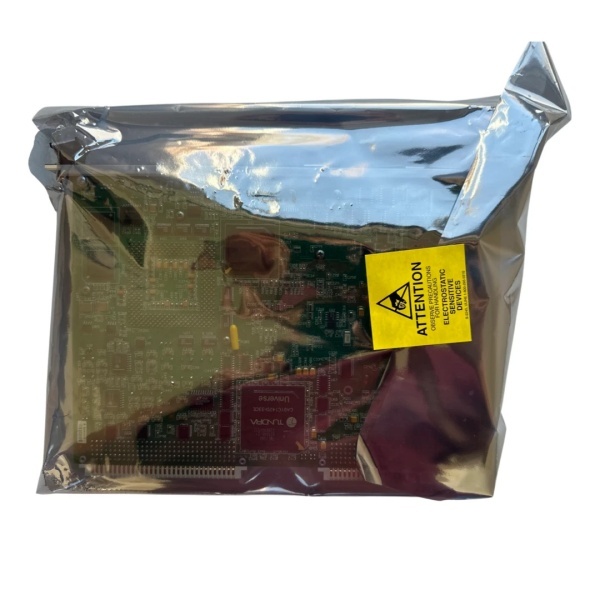
IS215UCVFH2A
The Real-World Problem It Solves
Not every application needs a full-scale Mark VIe rack. The IS215UCVFH2A integrates PLC controller and digital I/O in a compact package, perfect for auxiliary systems like lube oil pumps, cooling fans, and HVAC control panels. It connects directly to GE PACSystems networks for seamless integration with main turbine control.
Where you’ll typically find it:
- Gas turbine auxiliary lube oil pump control panels
- Steam turbine bearing temperature monitoring systems
- Small industrial applications requiring standalone PLC control with network connectivity
Bottom line: It gives you standalone PLC capability with digital I/O in a compact, rugged package.
Hardware Architecture & Under-the-Hood Logic
The IS215UCVFH2A is an embedded PLC with integrated digital I/O. The Marvell ARM processor runs Windows Embedded Compact 7 operating system and Mark VIe Compact runtime. The controller includes 16 digital inputs (24VDC sinking/sourcing) and 8 digital outputs (24VDC relay contacts). Expansion modules are supported via backplane connector for analog I/O or additional digital I/O. Ethernet port supports GE SRTP protocol for high-speed communication with PACSystems main controllers. Serial port supports Modbus RTU for third-party device integration. USB host port supports HMI programming and data logging. The controller can operate standalone using embedded logic engine or as a distributed I/O node under PACSystems main controller. The firmware supports IEC 61131-3 programming languages (Ladder Logic, Structured Text, Function Block Diagram, Instruction List, Sequential Function Chart). The device supports digital filtering, timer/counter functions, and data logging to USB flash memory.
Internal signal flow:
- Digital input signal arrives at terminal block (24VDC)
- Signal passes through protection circuits (TVS diodes for transient protection)
- Signal drives optoisolator LED, creating isolated logic signal
- Logic signal is latched into input register
- Processor executes logic program (Ladder Logic or Structured Text)
- Output logic drives relay contacts or expansion outputs
- Ethernet port establishes SRTP or Modbus TCP connections to main controller
- Data logging streams to USB flash memory if enabled
- Operator inputs from HMI update process variables sent to main controller
- Front-panel LEDs reflect power status, logic status, and communication status
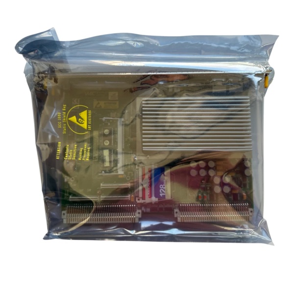
IS215UCVFH2A
Field Service Pitfalls: What Rookies Get Wrong
Overloading relay outputs causes premature failureThe relay contacts are rated for 5A at 24VDC or 0.5A at 120VAC. I’ve seen technicians drive heavy loads (10A motors) through the contacts, leading to contact welding and relay replacement.
- Field Rule: Never exceed relay contact ratings for continuous operation. Use external contactors or motor starters for loads over 5A. If contact welding occurs, replace the relay module immediately. Document contact ratings in your maintenance procedure.
Failing to download logic to the controllerThe PLC operates based on the program stored in flash memory. I’ve seen technicians commission the controller without downloading the latest logic program, resulting in outdated control behavior.
- Field Rule: Always download the latest logic program from Mark VIe software after installation. Verify the program version matches the version in your configuration management system. Perform a test run with logic enabled to ensure proper operation. Document program version and download date in your maintenance log.
Ignoring network security creates unauthorized accessThe Ethernet port provides network connectivity but needs proper security. I’ve seen controllers with default factory passwords enabled, allowing unauthorized changes to logic and parameters.
- Field Rule: Set strong passwords for access to the controller via Ethernet. Change default factory passwords immediately after commissioning. Restrict IP address access to only authorized main controllers or workstations. Enable firewall rules if supported by the controller. Document security settings in your network management plan.
Improper grounding causes communication failureThe controller requires a solid earth ground reference for proper operation and EMI suppression. I’ve seen controllers with intermittent communication because technicians left the ground floating.
- Field Rule: Bond the controller’s chassis ground terminal to the cabinet ground. Use a minimum #12 AWG solid wire for ground connection. Maintain ground continuity between the controller and main PACSystems rack. Measure ground potential difference—should be less than 1VAC.
Forgetting to test digital output polarityThe relay outputs are optoisolated, but polarity matters for loads. I’ve seen technicians wire a load to the common and normally open terminals, only to find the polarity reversed, causing the load to not activate.
- Field Rule: Test each digital output for proper polarity and operation. Use a multimeter to verify voltage across the relay contacts when activated. Document relay contact configuration (NO/NC) per output channel in your control system database.
Not backing up logic program before serviceThe embedded flash memory can fail or corruption can occur. I’ve seen technicians perform firmware updates without backing up the logic program, resulting in lost logic when the flash becomes corrupted.
- Field Rule: Back up the logic program to USB flash memory after commissioning and before any service action (firmware update, module replacement). Store backup copies on network drives for redundancy. Document backup version and location in your CMMS.
Commercial Availability & Pricing Note
Please note: The listed price is for reference only and is not binding. Final pricing and terms are subject to negotiation based to current market conditions and availability.


