
Description
Product Introduction
The GE is a critical power electronic module designed for industrial drive systems. It effectively clamps voltage spikes generated during IGBT switching events. This action protects expensive power semiconductors from destructive transient overvoltages.
This module features a reinforced PCB layout optimized for high dv/dt ratios. It integrates seamlessly with GE’s IS200 series drive controllers. The “H2A” revision offers improved thermal management over earlier versions. Well, technically it handles 20kHz switching, but only with proper heat sinking. We typically see a 10+ year service life in the field—though high-vibration panels may loosen the larger electrolytic capacitors on the GE .
Key Technical Specifications
| Parameter | Value |
|---|---|
| DC Link Voltage | 600 V DC (Max) |
| Switching Frequency | 20 kHz (Typical) |
| Continuous Current | 15 A (Verify with OEM datasheet) |
| Operating Temp | -20°C to +85°C |
| Storage Temp | -40°C to +90°C |
| Capacitance (Snubber) | 4.7 µF (Typical) |
| Mounting Style | Chassis Mount / Standoff |
| Communication | Hardware Logic (No bus comms) |
| Dimensions (Approx.) | 150 mm x 100 mm x 25 mm |
| Weight (Approx.) | 0.35 kg |
IS215ISBBH2A
Quality Control Process
- Incoming Verification: Trace lot numbers against GE manufacturing records. Check for counterfeit components and physical damage. Inspect for cracked solder joints on high-current tabs under magnification.
- Live Functional Test: Connect the module to a dynamic brake test rig. Cycle the IGBT gate signals at 20kHz for 24 hours. Monitor heat sink temperature and thermal rolloff.
- Electrical Parameter Test: Verify DC link isolation using a 1000V Megger, checking for breakdown above 20 MΩ. Measure snubber capacitor ESR with an LCR meter.
- Firmware Verification: N/A (Purely hardware logic board). Verify jumper settings and trace continuity for gate driver circuits.
- Final QC & Packaging: Clean the PCB with electronic-grade solvent. Wrap in anti-static foam. Apply QC Passed label with date and technician signature.
Replacement Pitfall Guide
❗ Firmware Mismatch: N/A for this hardware-logic board, but ensure the host drive firmware supports the H2A timing characteristics.
❗ DIP Switch / Jumper Misconfiguration: Factory jumper settings dictate the gate resistor values. Ensure these match your specific IGBT module to prevent shoot-through on the GE .
❗ Terminal / Cable Incompatibility: High dv/dt requires tight grounding. Double-check the shield termination on the main DC bus links of the GE .
❗ Power Supply Mismatch: Verify the 24V auxiliary supply can handle the gate driver inrush. Undersized wiring causes erratic IGBT triggering.
❗ ESD Damage: Gate driver circuits are extremely sensitive. Use an anti-static mat and wrist strap during installation of the GE .
Keep these in mind and you’ll cut 90% of rework time.
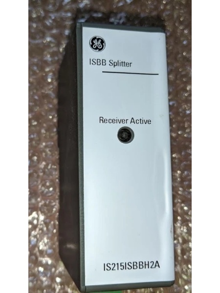
IS215ISBBH2A
Compatibility Matrix & Benchmarks
- IS215ISBBH1A → : Direct — Drop-in replacement with better thermal capacity.
- IS200ISBBG1A → : Needs Adaptation — Requires panel rewiring and different standoff mounting.
- → IS215ISBBH3A : Incompatible — Higher voltage rating exceeds this board’s 600V limit.
- Switching Loss: 12W (Typical at 20kHz, 15A load)
- Thermal Rise: 35°C (Above ambient, 400 LFM airflow)


