
Description
Hard-Numbers: Technical Specifications
- Number of Channels: 16 digital inputs (DI)
- Input Type: 24VDC (sinking/sourcing) or 120VAC (selectable per channel)
- Voltage Range: 20-30VDC (DI) or 100-127VAC (DI)
- Current Consumption per Channel: 10 mA @ 24VDC, 0.25A @ 120VAC
- Input Filter (Debounce): 1ms, 3ms, 7ms, 15ms, 30ms, or 100ms (software-configurable)
- Response Time: 1ms (fast) or up to 100ms (filtered)
- Isolation: 1500V RMS between input channels and backplane
- Module Power Draw: 2.5A @ 5VDC from backplane
- Backplane Current: 5V: 2.5A max
- Operating Temperature: -20°C to 70°C (-4°F to 158°F)
- Storage Temperature: -40°C to 85°C (-40°F to 185°F)
- LED Indicators: PWR, OK, FAULT, COMM (backplane communication), individual channel status LEDs
- Cooling: Forced air (requires Mark VIe backplane cooling)
- Field Termination: Standard 36-pin terminal block (GE part number IS200VTURH1B terminal block or equivalent)
- Module Slot: Mark VIe I/O backplane (any slot in expansion rack)
- Communication: Backplane via TCP/IP (embedded I/O processor)
- Firmware Version: Compatible with Mark VIe v6.0 and later
- Input Rating: NEMA 6P (waterproof for outdoor cabinets when properly sealed)

GE IS210AEDBH4AGD
The Real-World Problem It Solves
Digital I/O is the foundation of turbine control systems—monitoring limit switches, safety interlocks, and status signals. The IS210AEDBH4AGD packs 16 inputs into a single module, reducing rack space and wiring complexity. The configurable debounce filtering eliminates false triggers from noisy switches and sensors.
Where you’ll typically find it:
- Gas turbine control cabinets monitoring safety interlocks (emergency shutdown)
- Steam turbine governor systems tracking limit switches and position sensors
- Generator control racks with digital status inputs
Bottom line: It gives you high-density digital input with debounce filtering for clean status signals.
Hardware Architecture & Under-the-Hood Logic
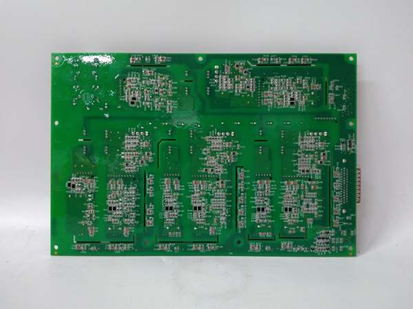
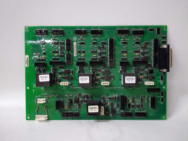
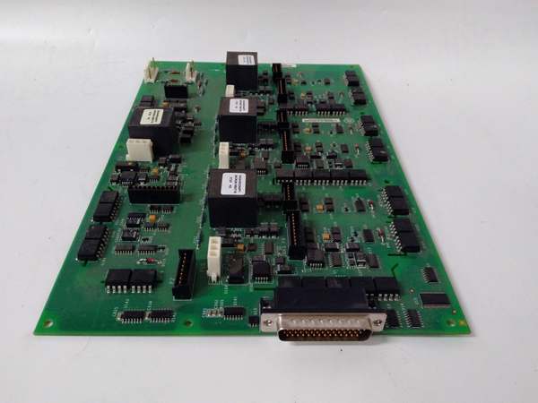
The IS210AEDBH4AGD is a high-density digital input module for Mark VIe turbine control racks. Each of the 16 channels has dedicated signal conditioning, optoisolator, and configurable debounce filtering. The module supports both 24VDC (sinking/sourcing) and 120VAC inputs, selected via software configuration for each channel. The optoisolator provides 1500V isolation between field inputs and backplane, protecting the controller from electrical noise and voltage transients. The debounce filter (1-100ms) software-configurable to suppress contact bounce from switches and sensors. An embedded ARM processor manages channel configuration, data formatting, and backplane communication. Channel configuration (filter, voltage range, polarity) is set via Mark VIe software and stored in non-volatile memory. Data is transmitted to the main controller via backplane TCP/IP at 100 ms update rate. The module includes LED status indicators for each channel to provide local visual feedback.
Internal signal flow:
- Digital input signal arrives at terminal block (24VDC or 120VAC)
- Signal passes through protection circuits (TVS diodes for transient protection)
- Signal is filtered through configurable debounce filter (software setting)
- Signal drives optoisolator LED, creating isolated logic signal
- Logic signal is latched into input register
- Input status is buffered for backplane transmission
- Embedded processor formats data into Ethernet packets
- Processor communicates with main controller via backplane TCP/IP
- Channel status and diagnostic data are generated for monitoring
- Front-panel LEDs reflect power status, communication status, and channel faults
GE IS210AEDBH4AGD
Field Service Pitfalls: What Rookies Get Wrong
Mixing voltage types on the same module causes damageThe IS210AEDBH4AGD supports both 24VDC and 120VAC inputs, but they must be configured per channel. I’ve seen technicians wire a 120VAC signal to a channel configured for 24VDC, frying the optoisolator and potentially damaging the backplane.
- Field Rule: Configure each channel for the actual input voltage type in Mark VIe software before wiring. Verify jumper settings for voltage range if using physical jumpers. Test each channel with a multimeter to confirm voltage levels match configuration. Document channel configuration per voltage type in your asset management system.
Forgetting debounce filtering causes false triggersMechanical switches have contact bounce. I’ve seen technicians use 1ms filtering (fast response) on limit switches, resulting in multiple false triggers and erroneous emergency shutdowns.
- Field Rule: Set debounce filter based on sensor type. Limit switches and electromechanical devices: 30ms debounce to suppress contact bounce. Proximity sensors and solid-state devices: 1-3ms debounce for fast response. Configure filtering in Mark VIe software and test actual switch performance. Document filter settings in your maintenance procedure.
Ignoring grounding creates ground loops and false inputsDigital inputs are sensitive to ground loops and common mode noise. I’ve seen random inputs turn on when they shouldn’t because the sensor ground was connected to a different reference than the module ground.
- Field Rule: Use single-point grounding for all field devices connected to the IS210AEDBH4AGD. Tie all sensor grounds to the module ground reference at the terminal block. Never connect sensor grounds to earth ground at both ends—this creates ground loops. Measure ground potential difference between module ground and sensor ground—should be less than 0.5VAC.
Incorrect wiring of sinking/sourcing inputsThe module supports both sinking (NPN) and sourcing (PNP) digital inputs. I’ve seen technicians wire a PNP sensor to a channel configured for NPN, resulting in inputs that never read high.
- Field Rule: Verify sensor type (NPN sinking or PNP sourcing) and configure the channel accordingly in Mark VIe software. For sinking inputs, the field device pulls the signal low. For sourcing inputs, the field device provides 24VDC. Document sensor type per channel in your control system database.
Leaving unused channels floating causes undefined behaviorUnused digital inputs left open circuit can float between low and high states due to noise, creating false status signals.
- Field Rule: Tie unused channels to ground or positive supply to avoid floating. For sinking inputs, tie unused channels to ground via 1kΩ resistor. For sourcing inputs, tie unused channels to positive via 1kΩ resistor. Never leave digital inputs unterminated—this can cause false triggers and diagnostic faults.
Testing digital inputs without considering safety interlocksSafety interlocks (like emergency shutdown) are critical. I’ve seen technicians trigger interlock signals during testing and accidentally trip the turbine, leading to unexpected downtime.
- Field Rule: Always disable logic before testing safety interlock inputs. Use Mark VIe software’s “force inputs” feature to simulate interlock states instead of wiring real signals. Perform lockout-tagout (LOTO) before working on safety interlock circuits. Document safety testing procedures in your maintenance manual.
Commercial Availability & Pricing Note
Please note: The listed price is for reference only and is not binding. Final pricing and terms are subject to negotiation based to current market conditions and availability.


