
Description
Hard-Numbers: Technical Specifications
- Compatible Systems: Mark V (Speedtronic) Gas & Steam Turbine Controls
- Core Integration: R1, R2, R3 I/O Cores (Interfaces directly with TCPS, STCA, TCQC, and TBQA boards)
- Signal Types Supported: 4-20mA Inputs/Outputs, LVDT Inputs, Thermocouples, Vibration Sensors, Pulse Inputs
- Key Connectors: 2PL (Power), 3PL (COREBUS Data), JA/JB/JD/JE (Field & Inter-board Signals)
- Operating Temperature: 0°C to +60°C (Standard industrial control environment)
- Communication Protocol: COREBUS (Mark V Internal Backplane Bus)
- Mounting: Mark V I/O Core Card Cage (Right-hand or dedicated I/O slots)
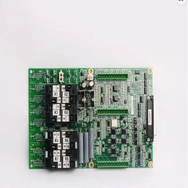
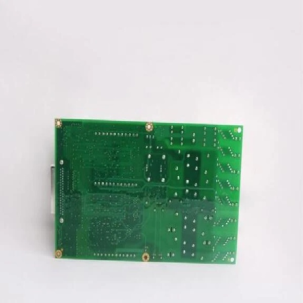
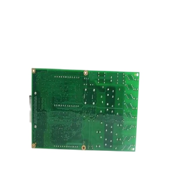
IS210AEAAH1B
The Real-World Problem It Solves
You are maintaining a legacy GE Frame 7FA gas turbine controlled by a Mark V Speedtronic system. The turbine is experiencing erratic exhaust temperature readings and intermittent “Fuel Flow Pressure” alarms. After tracing the wires, you determine that the analog I/O board responsible for scaling these 4-20mA signals has failed. Because the Mark V architecture relies on dedicated, highly specialized analog conditioning boards, you cannot simply drop in a generic modern I/O module. You need an exact functional replacement—the IS210AEAAH1BBA—to restore the precise signal scaling for the compressor stall detection and fuel valves without rewriting the turbine’s control logic .
Where you’ll typically find it:
- Mark V I/O Cores (R1, R2, R3): Mounted in the card cages of legacy control panels, acting as the primary interface between field transmitters and the main processor .
- Gas Turbine Fuel Systems: Processing 4-20mA feedback from fuel flow transmitters and command signals to liquid fuel bypass valves .
- Steam Turbine Control Cabinets: Handling LVDT inputs for valve positioning and 4-20mA outputs for boiler feedwater pump speed control .
It acts as the critical analog front-end for the Mark V controller, ensuring that raw, noisy field signals are accurately converted into stable data that the turbine’s protection algorithms can trust.
Hardware Architecture & Under-the-Hood Logic
The “BBA” suffix denotes a specific manufacturing revision of the Mark V Analog I/O (TCQA) board. Unlike modern networked I/O packs, the IS210AEAAH1BBA is a highly integrated, bus-centric board designed to work in concert with other Mark V core boards.
- Centralized Signal Conditioning: The board is engineered to take raw analog signals from field devices (like 4-20mA pressure transmitters or millivolt-level thermocouples) and perform hardware-level scaling and linearization. It filters out electrical noise from nearby VFDs and high-voltage contactors before passing the cleaned-up data to the main processor via the 3PL COREBUS connector .
- Inter-Board Communication via 3PL & JE: The 3PL connector links the board to the STCA (Sequence & Trip Control) and TCQE boards, ensuring that critical trip signals and control sequences are synchronized across the core. The JE connector specifically handles pulse signals, generator/line signals, and servo valve drivers, making the BBA essential for closed-loop control .
- Hardware Redundancy Support: In a triple-redundant Mark V setup (R1, R2, R3), this board processes the analog inputs for its respective core. The Mark V system constantly compares the analog readings from three separate BAAs across the R1, R2, and R3 cores. If one board drifts out of spec or fails, the system votes it out, allowing the turbine to keep running safely without a sudden trip .
IS210AEAAH1B
Field Service Pitfalls: What Rookies Get Wrong
Misaligning the 3PL Ribbon Cable During Hot-Swapping
A technician needs to replace a faulty BBA in a running Mark V core (e.g., R2). He carefully unplugs the field wiring (JB/JE) and the power (2PL), but in his haste, he pulls directly on the 3PL ribbon cable instead of using the release tabs. He damages the fragile ribbon cable or bends the pins on the STCA board.
- The Mistake: The 3PL is a multi-pin ribbon connector that is extremely delicate. Applying uneven force or pulling from the wire instead of the plastic housing almost always results in bent pins or broken traces, which can disable the entire core’s communication bus.
- Field Rule: NEVER pull a 3PL cable by the wires. Always use a flathead screwdriver or your fingers to gently squeeze the release tabs on the sides of the connector and pull straight back from the plastic housing. If the connector is stuck, wiggle it gently. If pins get bent, do not try to straighten them in the live rack; remove the board and use a magnifying glass and fine-tip tweezers to carefully realign them.
Ignoring the “RST” Common Reference During Wiring
An engineer is commissioning a new fuel gas pressure transmitter and connecting it to the terminal block (TBQA) that feeds the BBA. He wires the 4-20mA signal according to the loop drawing, but the Mark V HMI reads “0 mA” or shows wildly oscillating values.
- The Mistake: In the Mark V architecture, many analog inputs (especially for LVDTs and specific 4-20mA loops) share a common reference plane known as “RST.” The engineer likely connected the negative leg of the transmitter to a generic DC ground (DGND) or left it floating, breaking the differential measurement circuit required by the BBA’s analog-to-digital converters.
- Quick Fix: Always verify the termination type in the Mark V wiring diagrams. If the input is specified as “Differential” or references “RST,” you must connect the negative lead of the field device directly to the designated RST terminal on the TBQA terminal board. Mixing RST and DGND grounds is a classic rookie error that leads to uncalibrated or noisy analog readings.


