
Description
Hard-Numbers: Technical Specifications
- Number of Channels: 8 analog input channels
- Input Type: 4-20 mA, 0-20 mA, 0-10 VDC, ±10 VDC (configurable per channel)
- Resolution: 16-bit (up to ±0.015% full scale)
- Accuracy: ±0.1% full scale typical
- Sampling Rate: 1 kHz per channel
- Common Mode Rejection: 70 dB typical at 60 Hz
- Input Impedance: 10 MΩ for voltage inputs; 250 Ω for current inputs (jumper selectable)
- Software-Configurable Filters: Low-pass (10 Hz, 50 Hz, 250 Hz, 1 kHz), high-pass, bandpass, notch (60 Hz)
- Isolation: 1500V RMS between channels and backplane; 500V RMS between channels
- Module Power Draw: 2.0A @ 5VDC from backplane
- Backplane Current: 5V: 2.0A max
- Operating Temperature:** -20°C to 70°C (-4°F to 158°F)
- Storage Temperature: -40°C to 85°C (-40°F to 185°F)
- LED Indicators: PWR, OK, FAULT, individual channel status LEDs
- Cooling: Forced air (requires Mark VIe backplane cooling fan)
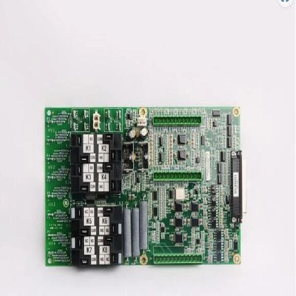
- Field Termination: Standard 36-pin terminal block (GE part number IS200EPSG1A or equivalent)
- Module Slot: Mark VIe I/O backplane (any slot in expansion rack)
- Communication: Backplane via TCP/IP (embedded I/O processor)
- Firmware Version: Co
mpatible with Mark VIe v7.0 and later
- Calibration: Self-calibrating with external reference capability (traceable calibration supported)

GE IS210AEAAH1B
The Real-World Problem It Solves
Turbine control systems need accurate analog measurements for governor control and monitoring. The IS210AEAAH1B delivers 16-bit resolution with configurable filtering for clean data in noisy environments. Your control loops see the true process variable, not corrupted by electrical noise or ground loops.
Where you’ll typically find it:
- Gas turbine control cabinets monitoring temperatures, pressures, and flow rates
- Steam turbine governor systems with analog feedback loops
- Generator excitation systems with voltage and current measurement
Bottom line: It gives you high-resolution analog input with noise filtering for critical control loops.
Hardware Architecture & Under-the-Hood Logic
The IS210AEAAH1B is a high-performance analog input module for Mark VIe I/O racks. Each of the 8 channels has dedicated signal conditioning circuits, including protection (TVS diodes), programmable gain amplifier, anti-aliasing filter, and a 16-bit ADC. The module supports both current (4-20 mA, 0-20 mA) and voltage (0-10 V, ±10 V) inputs, selected via hardware jumpers and software configuration. The embedded ARM processor manages channel configuration (gain, filter, range), data formatting, and backplane communication. Sampling parameters (rate, filter type) are configured via Mark VIe software and stored in non-volatile memory. The module includes a self-calibration routine that uses an internal voltage reference to compensate for offset and gain drift. Data is transmitted to the main controller via backplane TCP/IP at 1 kHz update rate, ensuring low latency for control loops. The software-configurable filtering supports low-pass, high-pass, bandpass, and notch (60 Hz) filters for noise rejection without sacrificing response time.
Internal signal flow:
- Analog field signal arrives at terminal block (current or voltage)
- Signal passes through protection circuits (TVS diodes for transient protection)
- Current inputs pass through shunt resistor to convert to voltage
- Programmable gain amplifier adjusts signal level for ADC range
- User-configurable filter (low-pass, high-pass, bandpass, or notch)
- Anti-aliasing filter (low-pass) removes frequencies above Nyquist
- Sample-and-hold circuit freezes voltage at specified sampling rate
- 16-bit ADC converts analog signal to digital value
- Digital data is transferred to channel buffer
- Embedded processor formats data into Ethernet packets
- Processor communicates with main controller via backplane TCP/IP
- Channel status and diagnostic data are generated for monitoring
- Front-panel LEDs reflect power status, communication status, and channel faults
GE IS210AEAAH1B
Field Service Pitfalls: What Rookies Get Wrong
Mismatching input range causes saturation and measurement errorsThe IS210AEAAH1B has multiple configurable input ranges. I’ve seen technicians set a channel for 0-10V but wire a 4-20mA sensor, resulting in invalid readings or full-scale offsets.
- Field Rule: Always match the channel configuration to the actual sensor output range. Verify jumper settings for current/voltage inputs on the terminal block. Use the Mark VIe software to configure each channel’s gain and range. Document channel configurations in your control system database.
Improper grounding creates ground loops and offsetsGround loops are the enemy of accurate analog measurement. I’ve seen channels with fixed 5% offset because the sensor ground was connected to a different reference than the module ground.
- Field Rule: Use single-point grounding for all field sensors connected to the IS210AEAAH1B. All sensor grounds should tie to the module ground reference at the terminal block. Never connect sensor grounds to earth ground at both ends—this creates ground loops. Measure ground potential difference between module ground and sensor ground at the field device—should be less than 1VAC.
Incorrect filter settings delay control loop responseThe module offers multiple filter options. I’ve seen operators configure 10 Hz low-pass filters for fast flow control loops, causing sluggish response and instability.
- Field Rule: Set filter frequency based on your control loop dynamics. Fast flow and pressure loops: 250 Hz or 1 kHz low-pass. Temperature and slow loops: 50 Hz low-pass. For 60 Hz noise rejection without phase lag, use the notch filter tuned to 60 Hz. Document filter settings in your loop tuning records.
Leaving unused channels floating induces noise pickupUnused analog channels are susceptible to noise injection. I’ve seen valid channels affected by random spikes because adjacent unused channels were left open circuit.
- Field Rule: Terminate unused voltage channels with 1 MΩ resistors to ground. Terminate unused current channels with short-circuit jumpers across the input terminals. Never leave analog channels unterminated—this creates antenna-like noise pickup that can affect adjacent channels. Document unused channel termination status in your installation records.
Ignoring self-calibration leads to measurement driftThe module includes a self-calibration feature that compensates for offset and gain errors. I’ve seen technicians ignore the annual calibration procedure, leading to measurement drift up to 0.5% full scale.
- Field Rule: Perform self-calibration of the IS210AEAAH1B at least once annually. Calibrate in a temperature-stable environment (25°C recommended). If your application requires traceable calibration, use an external calibration standard (e.g., Fluke 744). Document calibration results in your maintenance log. If drift exceeds ±0.2% full scale, replace the module.
Wrong wire gauge causes voltage drop on current loopsCurrent loop accuracy depends on loop resistance. I’ve seen technicians use 24AWG wire for 1000-foot runs, resulting in voltage drop that causes the transmitter to saturate before reaching 20 mA.
- Field Rule: Size wire for loop resistance. Calculate total loop resistance (wire resistance + load resistor + transmitter internal resistance). Keep total loop resistance below 600 Ω for 24VDC transmitters. Use 18-20 AWG for long runs (over 500 feet). Measure loop current at both transmitter and module to verify consistency.
Commercial Availability & Pricing Note
Please note: The listed price is for reference only and is not binding. Final pricing and terms are subject to negotiation based to current market conditions and availability.


