
Description
Hard-Numbers: Technical Specifications
- Analog Inputs: 8 Channels (Configurable 4-20mA DC or 0-10V DC)
- Input Accuracy: ±0.05% of Full Scale at 25°C
- Analog Outputs: 4 Channels (Configurable 4-20mA DC or 0-10V DC)
- Output Accuracy: ±0.1% of Full Scale at 25°C
- Resolution: 16-bit (Both Input and Output)
- Signal Isolation: 1500V AC Channel-to-Channel, 2500V AC Channel-to-Ground
- Communication Interface: GE Serial Peripheral Interface (SPI) / IONet
- Operating Voltage: 24V DC (Nominal)
- Operating Temperature: -40°C to +85°C (Wide range for harsh environments)
- Update Rate: 5ms (Inputs), 10ms (Outputs)
- Diagnostics: Open-circuit/short-circuit detection, output drift monitoring, overcurrent protection, and LED status indicators
- Dimensions: Approx. 120mm (W) x 180mm (H) x 220mm (D)
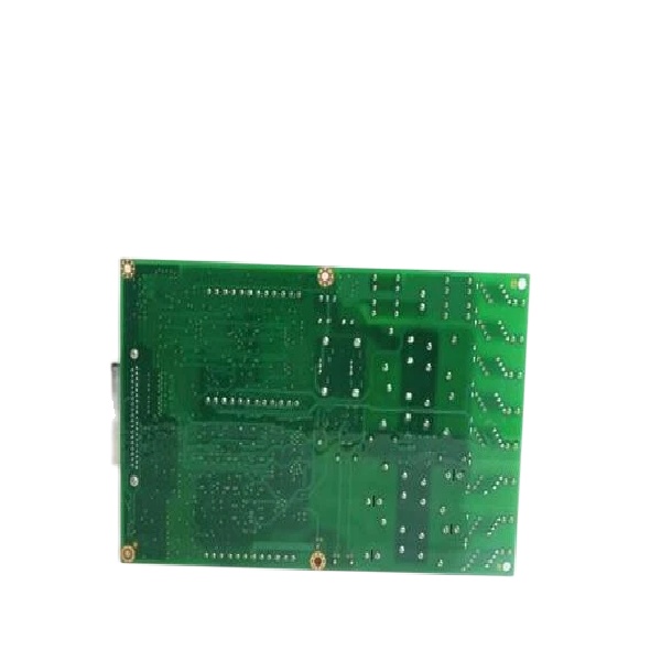
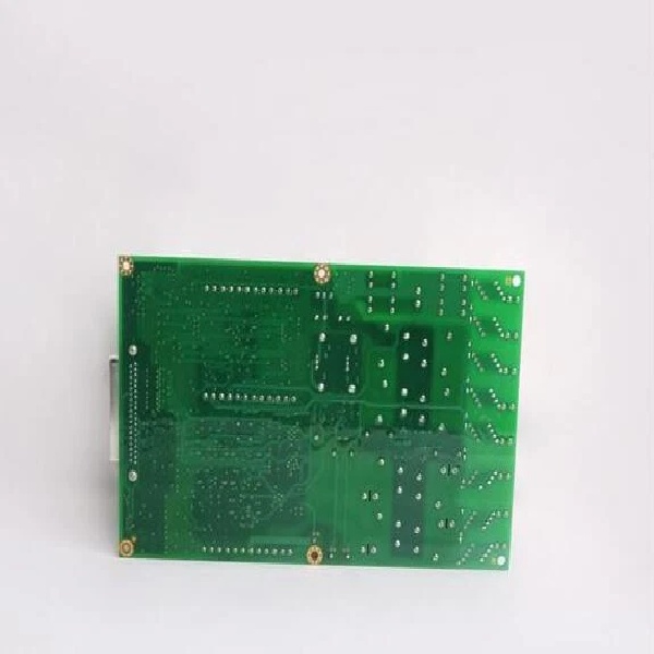
IS210AEAAH1B
The Real-World Problem It Solves
You are retrofitting an older Mark VI turbine panel that originally used separate, single-function analog input (TCQA) and output (TCQE) boards. The I/O rack is completely maxed out, and you have no physical slot space left to add monitoring for a new compressor stall detection system. You need to consolidate your analog I/O footprint without sacrificing signal precision or system reliability. The IS210AEAAH1B solves this by packing 8 high-speed analog inputs and 4 outputs into a single, Mark VIe-compatible module, freeing up valuable rack space while handling the 4-20mA signals required for modern stall detection and fuel flow control .
Where you’ll typically find it:
- Gas & Steam Turbine Control Cabinets: Processing critical 4-20mA feedback loops from combustion chamber pressure transmitters, exhaust thermocouples, and fuel valve positioners .
- Wind Turbine Nacelles (Mark VIe): Managing the analog I/O for pitch control systems and generator monitoring, where its wide operating temperature (-40°C to +85°C) is essential .
- EX2100 Excitation Systems: Providing the high-resolution analog outputs needed to drive thyristor firing circuits, alongside inputs monitoring generator voltage and current .
It acts as a compact, high-density bridge between the raw analog field instrumentation and the main Mark VIe turbine controller, filtering noise and executing deterministic control loops to maintain grid stability.
Hardware Architecture & Under-the-Hood Logic
The “H1B” suffix denotes a specific hardware configuration within the AE (Acquisition & Excitation) series. Unlike older, monolithic Mark VI boards that relied heavily on the VME backplane, the IS210AEAAH1B operates as a highly independent, intelligent I/O node .
- Integrated Signal Conditioning & 16-bit Precision: The module features dedicated, independently isolated ADCs and DACs for each channel. This means a massive inductive transient on Input Channel 1 (e.g., from a shorted pressure transmitter) will not cause a voltage sag or reading error on Channel 2. The 16-bit resolution allows the Mark VIe processor to detect minute changes in turbine parameters, such as a 0.001% shift in fuel pressure, enabling tighter combustion control .
- Hardware-Level Diagnostics: The AE series shifts some of the burden away from the main processor. The IS210AEAAH1B continuously runs self-tests on its own outputs (detecting “drift” where a 12mA output might silently degrade to 11.5mA) and actively monitors input lines for open or short circuits. If a field wire breaks on a critical 4-20mA stall detection loop, the module detects the “open circuit” instantly and reports it back to the controller via SPI/IONet, allowing for a controlled turbine ramp-down rather than a sudden, unexplained trip .
- Seamless SPI/IONet Integration: Data is packaged locally within the module and transmitted to the main controller over a high-speed serial link (SPI) or Ethernet (IONet). This drastically reduces the amount of noisy, analog wiring running through the cabinet and makes the module hot-swappable in redundant configurations, as the main processor simply sees it as another node on the network rather than a directly mapped memory address .
IS210AEAAH1B
Field Service Pitfalls: What Rookies Get Wrong
Assuming Pinouts Match Legacy Mark VI Boards
A technician is replacing an obsolete, separate analog input board with the new, consolidated IS210AEAAH1B to save space. He reuses the existing wiring, connecting the 4-20mA field devices to the corresponding terminals based on the old board’s documentation. Upon powering up, the system throws “Input Out of Range” errors, and the HMI shows wildly fluctuating values.
- The Mistake: While the IS210AEAAH1B is designed for the Mark VI/VIe ecosystem, its terminal assignments (pinouts) for the 8 inputs and 4 outputs do not directly map to the legacy 3PL or JE connectors used by older TCQA/TCQE boards . Connecting 24VDC power to a signal pin, or swapping the positive and negative legs of a 4-20mA loop on the new terminal block, will result in immediate communication failure or damaged input buffers.
- Field Rule: Never assume “like-for-like” physical mounting means “like-for-like” wiring. Always download the specific cabling and terminal block wiring diagramfor the IS210AEAAH1B from GE’s online support library (or your plant’s engineering docs) and verify every single wire connection before applying power.
Ignoring the 16-bit Scaling in Software
An engineer commissions a new to control a steam turbine’s main governor valve. The wiring is perfect, but when the Mark VIe controller commands a 50% open position (12mA), the physical valve only opens 25%.
- The Mistake: The engineer configured the output in the ToolboxST software as a standard 12-bit analog output (0-4095 raw counts) instead of utilizing the module’s native 16-bit resolution (0-65535 raw counts). This effectively cuts the precision and scaling range in half. Conversely, failing to configure the input scaling correctly can make a 0-100 psi pressure transmitter look like it’s reading in Bar or Kelvin, rendering the data useless.
- Field Rule: Spend the extra 10 minutes in the software configuration. Verify that the ToolboxST hardware definition file (.hwd) explicitly lists the , and double-check that your analog scaling blocks (Function Blocks) match the physical 4-20mA / 0-10V hardware jumpers and the module’s 16-bit data format. Test the full 0%, 50%, and 100% range with a precision calibrator before handing the system back to operations.


