
Description
Hard-Numbers: Technical Specifications
- Total Output Power: 400 Watts
- Input Voltage: 125 VDC (Nominal, from external Power Distribution Module)
- Output Voltages: +5 VDC, ±12 VDC, ±15 VDC, ±28 VDC
- Specialized Outputs: 335 VDC (Optional, for TRPG flame detectors), 28 VDC Remote (P28C/PS28 for external peripherals)
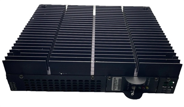
- Mounting Location: Right-hand side of the VME rack via sheet metal bracket
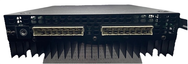
- Top Connectors: PSA, PSB (Cable harness to VME backplane)
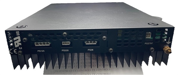
- Bottom Connectors: PS125/PS24 (Input), PS335, PS28, PSSTAT (Status)
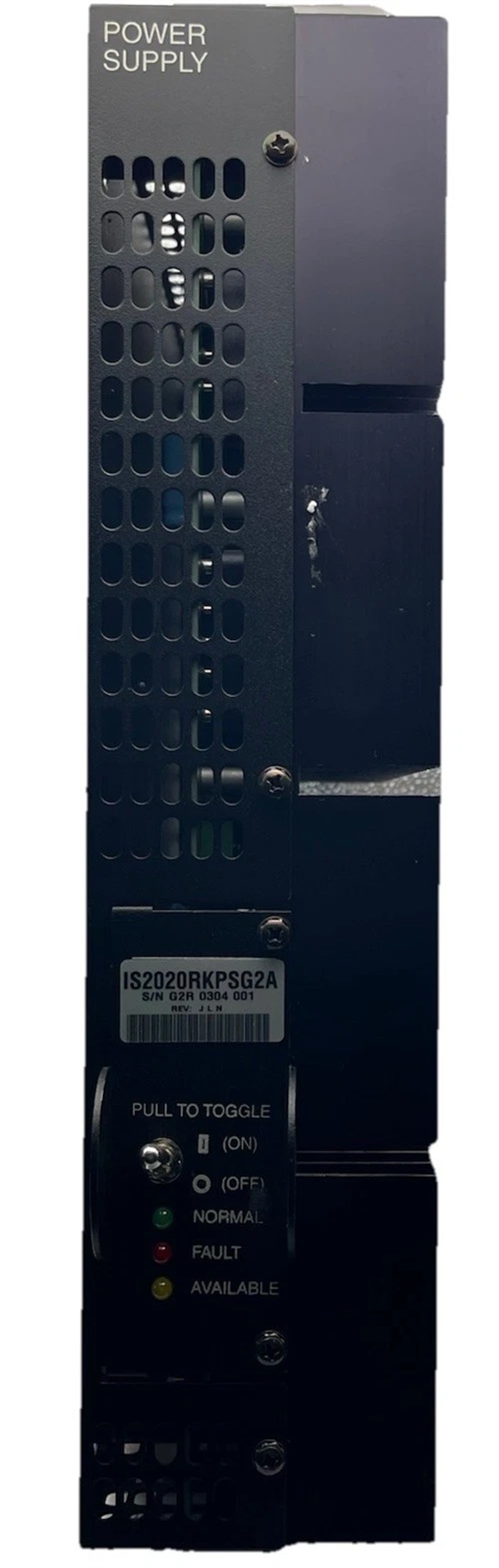
- Front Panel Controls: Locking toggle switch (On/Off/Fault Reset)
- Front Panel Indicators: Green (Normal), Yellow (Input Power), Red (Fault)
- Operating Temperature: 0°C to +60°C
- Agency Approvals: UL Listed, CE, CSA
GE IS2020RKPSG2A
The Real-World Problem It Solves
You are commissioning a Mark VIe panel for a gas turbine. The VME rack houses the primary processor, several I/O packs, and a TRPG (Triple Redundant Flame Detector). During the initial power-up, the 28VDC sensors and the flame detector array draw a massive inrush current. A standard, unregulated power supply would experience a severe voltage sag, potentially causing the processor to crash or the flame detectors to throw false loss-of-flame alarms. You need a heavy-duty, regulated power supply that can absorb these transient loads, provide a dedicated 335VDC clean source for the flame detectors, and actively alert the control room if its internal rails drift out of specification.
Where you’ll typically find it:
- Right Side of VME Racks: Bolted vertically onto the side of the main processor or I/O rack in Mark VI / Mark VIe panels, acting as the primary powerhouse for the entire rack’s logic and analog circuitry .
- Gas Turbine Control Cabinets: Specifically chosen for its ability to generate the high-voltage 335VDC rail required to excite GE’s TRPG flame detector scanners .
- Steam Turbine & Wind Turbine Drives: Providing the stable ±15VDC and ±28VDC analog rails needed for precise LVDT feedback and servo valve control .
It acts as the uninterruptible, hardened heart of the VME rack, ensuring that momentary sensor short-circuits or contactor inrush currents don’t ripple into the sensitive 5VDC processor logic.
Hardware Architecture & Under-the-Hood Logic
The “G2A” suffix denotes a specific hardware revision of the RKPS (Rack Power Supply) module. Unlike standard industrial power supplies, the RKPS is deeply integrated into the Mark VIe architecture’s fault-detection ecosystem .
- Cascaded Undervoltage Lockout (5V Logic Protection): The +5VDC rail is the most critical supply, powering the VME bus and processor cores. The RKPS monitors this rail closely. If the 5V output sags below a set threshold (due to an overload), the module triggers a “foldback” current limit. This intentionally drops the 5V output even further, forcing a system-wide undervoltage fault. By doing this, it cleanly shuts down the VME bus before erratic, half-powered logic signals can damage connected I/O boards or cause uncontrolled actuator movements .
- Galvanic Isolation & 335VDC Generation: The module incorporates a complex multi-tap transformer and high-frequency switching topology. This allows it to take a wide-range 125VDC input and simultaneously generate low-noise analog rails (±15V), digital rails (+5V), and a completely isolated, highly filtered 335VDC output specifically for flame detectors, ensuring EMI from the main turbine doesn’t affect combustion monitoring .
- Active Status Monitoring (PSSTAT): The RKPS doesn’t just power the rack; it communicates its health. Via the PSSTAT connector and the front-panel LEDs, it continuously reports AC OK, DC OK, and Overtemperature warnings back to the Mark VIe controller. If a cooling fan fails and the heatsink temperature rises, the RKPS will assert a fault and safely shut down before thermal damage occurs .
GE IS2020RKPSG2A
Field Service Pitfalls: What Rookies Get Wrong
Forgetting to Reconnect the PSA/PSB Ribbon Cables
A technician replaces a failed RKPS unit in a live rack. He carefully unbolts the unit, disconnects the bottom terminals (PS125, PS28, etc.), and installs the new unit. He powers up the rack, and the green LED illuminates. However, ten minutes later, the VME rack crashes, and the HMI reports “Loss of Processor Heartbeat.”
- The Mistake: The technician forgot to plug in the small, multi-pin ribbon cables (PSA and PSB) at the topof the RKPS. These cables carry the 28VDC power and status signals to the VME backplane. Without them, the processor and I/O boards are running on residual capacitor charge, which depletes rapidly, causing an uncommanded shutdown.
- Field Rule: Always double-check the top connectors. Make it a habit to mentally note: “Power in the bottom, distribution out the top.”
Misconfiguring the 28VDC Peripheral Jumper During Expansions
An integrator is adding a third-party vibration monitoring system to the turbine panel. They decide to power it using the RKPS’s auxiliary 28VDC output (P28C). They connect the wires to the PS28 terminal, but the device won’t power up, and the RKPS red fault light illuminates intermittently.
- The Mistake: The RKPS has a small jumper plug located near the top of the module (often on a bracket). By default, this jumper is in the “Normal” position, which ties the internal 28VDC rail to the VME rack sections. To use the PS28 terminal for externalperipherals, this jumper must be moved to the “Isolated” position. Leaving it in “Normal” while drawing heavy external current causes the internal current sensing to trip, flagging a false overcurrent fault.
- Field Rule: If powering devices outside the VME rack, always move the jumper to “Isolated” and ensure your external load doesn’t exceed the RKPS’s total 400W power budget.
Blocking the Heatsink Fins in High-Ambient Environments
A panel builder mounts the VME rack in a compact, sealed enclosure without calculating the thermal load. The RKPS is bolted to the side, but the panel designer placed a large variable frequency drive (VFD) directly next to it, and the cabinet’s exhaust fan is mounted too far away. After a month of summer operation, the RKPS fails catastrophically.
- The Mistake: The RKPS dissipates massive amounts of heat through the large metal fins on its side (the black anodized heatsink). In the confined space, ambient temperatures quickly exceeded the RKPS’s 60°C maximum operating limit. The internal overtemperature protection tripped, but the cyclical thermal stress cracked the solder joints on the main power transformer.
- Field Rule: The RKPS requires at least 3-4 inches of clearance around its heatsink fins for proper convection cooling. Never mount heat-generating devices (like VFDs or heavy contactors) directly adjacent to the RKPS. If the cabinet temperature exceeds 50°C, forced-air cooling (ventilation fans or an air conditioner) is mandatory.


