
Description
Hard-Numbers: Technical Specifications
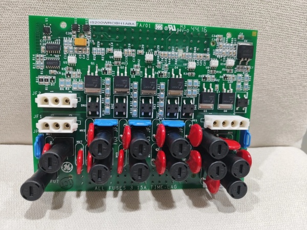
- Output Channels: 6 Fused/Sensed Relays + 1 Dedicated (Unfused) Relay Output
- Fuse Rating: 3.15A Fast-Blow (Rated for 500VAC / 400VDC handling)
- Compatible Host Boards: TDBS, SRLY, and TDBT Terminal Boards
- Redundancy Modes: Simplex, Dual-Redundant, or Triple Modular Redundant (TMR)
- Operating Voltage (Logic): 24VDC (Supplied from the host terminal board)
- Communication Interface: Modbus RTU (Via host TDBS board)
- Physical Dimensions: 37 cm W x 30 cm H x 4 cm D
- Operating Temperature: -30°C to +65°C (Non-condensing)
- Agency Approvals: UL Listed, CE, CSA (Compliant with industrial safety standards)
IS200WROBH1A
The Real-World Problem It Solves
You are designing the control panel for a critical natural gas compressor station. The Mark VIe controller needs to drive half a dozen 24VDC pneumatic solenoid valves and a few auxiliary 115VAC warning horns. The problem is that if a solenoid valve shorts out or draws excessive current, it could damage the main I/O rack or cause a nuisance trip, shutting down the entire compressor. You need a way to isolate these high-demand field loads, protect the controller from overcurrent events, and monitor the health of the output circuits in real-time.
Where you’ll typically find it:
- Mated to TDBS or SRLY Terminal Boards: Mounted as a daughterboard inside Mark VIe I/O racks to augment standard terminal boards with heavy-duty relay driving capabilities .
- TMR Turbine Protection Racks: Installed on TDBT terminal boards in Triple Modular Redundant systems to execute voting logic for fuel gas valves and lube oil pumps .
- Compressor Stations & Power Gen: Driving high-inertia contactors, solenoid banks, and alarm annunciators where individual branch circuit protection is mandatory .
It acts as the hardened, intelligent switchgear for your Mark VIe outputs, ensuring that a single stuck contactor coil doesn’t escalate into a costly system-wide shutdown.
Hardware Architecture & Under-the-Hood Logic
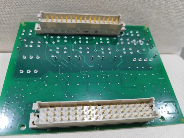
The “H1A” designation identifies this as a specific hardware revision of the WROB (Relay Fuse & Power Sensing Board). It is designed strictly as an option board—it cannot function as a standalone component. Instead, it plugs into the expansion header of a host terminal board (like the TDBS or SRLY) to offload and protect high-current discrete outputs .
- Fused Power Distribution & Sensing: The board takes the 24VDC power supplied by the host terminal board and distributes it across six independent fused channels. Crucially, it doesn’t just blow a fuse and go dark; internal sensing circuitry continuously monitors the voltage drop across each 3.15A fast-blow fuse. If a fuse opens due to an overcurrent event, the board instantly detects the change and reports a “Fuse Blown” status to the Mark VIe controller via the backplane .
- Load Isolation (TRLY Logic): The onboard relays act as a robust barrier between the sensitive 5VDC/24VDC logic of the Mark VIe processors and the noisy, high-inductive-kick field devices (like solenoids and relays). This prevents voltage transients from propagating back into the I/O rack .
- TMR Voting Capability: When deployed in a Triple Modular Redundant (TMR) configuration, three WROB boards work in parallel on a TDBT terminal board. The system employs “2-out-of-3” voting for the relay outputs, meaning the turbine or compressor will only trip if at least two of the three WROB modules agree that a shutdown condition has been met, effectively eliminating false trips caused by a single-point hardware failure .
IS200WROBH1A
Field Service Pitfalls: What Rookies Get Wrong
Swapping a 3.15A Fast-Blow Fuse with a Slow-Blow or Higher Amp Rating
A maintenance technician replaces a blown fuse on the WROB board. Not having a 3.15A fast-blow on hand, he grabs a 5A slow-blow fuse from his truck, thinking it will “hold up better” against the inductive kick of the solenoid valve. The next time the valve cycles, a minor internal short occurs. Because the 5A slow-blow didn’t trip as quickly as the designed 3.15A fast-blow, the excess current overheats the WROB board’s internal trace, destroying the board .
- Field Rule: Never up-fuse or change the time-delay characteristic of the WROB protection devices. The 3.15A fast-blow rating is precisely calculated to protect the board’s internal traces and the host terminal board’s power supply. Always carry spare 3.15A fast-blow fuses.
Installing the WROB on an Incompatible Terminal Board Version
An engineer is upgrading an older Mark VIe system. He orders an IS200WROBH1A to pair with an existing TDBS terminal board he found in the warehouse. He forces the connection, but the system won’t power up the outputs. The HMI reports “PDIO Option Board Not Detected.”
- Quick Fix: Not all terminal board revisions support all option boards. The TDBS board has multiple hardware revisions (e.g., TDBSH1, TDBSH2). Before ordering or installing a WROB, check the silkscreen on the host terminal board to ensure it has the correct option board expansion header populated. If the header is missing or the board revision is too old, the WROB simply won’t communicate with the controller .
Ignoring the Dedicated Output’s Separate Fusing Requirements
A panel builder is wiring the outputs for an emergency shutdown (ESD) horn and beacon. He uses the WROB’s dedicated (7th) unfused output because it wasn’t drawing much current. He assumes the 3.15A fuse rating applies to this output as well. A short circuit develops in the beacon’s wiring, drawing 10A. Since the dedicated output has no internal fuse, the massive current surge damages the WROB’s power bus and takes down the entire 24VDC supply for the I/O rack .
- Field Rule: The 7th “dedicated” output on the WROB is completely unfused. If you use this output, you must provide external fusing (appropriately sized for the load) in the field wiring before connecting it to the terminal block. Never assume the board will protect an unfused output.
Commercial Availability & Pricing Note
Please note: The listed price is for reference only and is not binding. Final pricing and terms are subject to negotiation based on current market conditions and availability.


