
Description
Hard-Numbers: Technical Specifications
- Input Voltage: 125 VDC, 115 VAC, or 24 VDC (Configurable per circuit)
- Number of Circuits: 2 Independent Power Distribution Circuits (PDCs)
- Output Capacity: 10A per circuit (Nominal)
- Fused Branches: 12 Total (6 branches per PDC)
- Fuse Rating: 3.15A at 25°C (Derated to 2.36A max at 65°C)
- Voltage Monitoring Delay: 60 ms typical maximum response delay
- Minimum Detection Voltage: 16 VDC, 72 VAC
- Physical Dimensions: 10.16 cm W x 33.02 cm H (4.0″ x 13.0″)
- Operating Temperature: -30°C to +65°C
- Mounting Style: TRLYH#F Daughterboard (Plugs into terminal board)
- Leakage Current (Max): 3 mA
IS200WETCH1A
The Real-World Problem It Solves
You are troubleshooting a Mark VIe steam turbine control panel. Multiple gas control valves have failed to open during a start-up sequence, and the HMI is displaying “Solenoid A Power Loss” alarms. A megger test confirms the valve coils are fine, but the 125VDC supply to the TRLY terminal board is dead. You trace the issue to a catastrophic short on one branch of the WPDF board that took out the entire power segment. Because the TRLY board lacks built-in power distribution, you need a robust daughterboard that can handle high-voltage solenoid loads, provide individual branch fusing, and feed power status back to the main I/O processors.
Where you’ll typically find it:
- Turbine Control Cabinets: Mounted as a daughterboard onto the TRLYH#F terminal board, distributing power to fuel gas valves, lube oil solenoid valves, and vent valves.
- High-Voltage I/O Racks: Sitting behind the main I/O processors (R, S, T) to provide localized, protected power for field devices.
- System Retrofits: Upgrading legacy relay-based power distribution to modern, monitored, and fused solid-state distribution.
It acts as the dedicated power guardian for your most critical turbine protective devices, ensuring a single shorted coil doesn’t cascade into a total control system failure.
Hardware Architecture & Under-the-Hood Logic
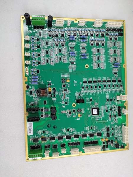
The WPDF (Power Distribution Board) is a highly specialized daughterboard designed specifically to work in tandem with the TRLYH#F terminal board. It is not a standalone module; it plugs directly into the TRLY to augment it with heavy-duty power distribution capabilities .
- Dual Independent Power Distribution Circuits (PDCs): The board supports two separate power feeds (e.g., 125VDC and 24VDC, or dual 115VAC). Each PDC can handle up to 10A nominal current, distributed across six fused branches .
- Precision Fusing and Protection: Each of the 12 output branches features a dedicated fuse. This ensures that if a field device (like a sticky solenoid valve) draws excessive current or shorts out, only that specific branch is disabled, protecting the rest of the control rack .
- Active Voltage Monitoring: Across the secondary of each fuse pair, a voltage monitor constantly samples the line. If a fuse blows or power is lost to a branch, the monitor detects the voltage drop (within 60ms) and fans out the alarm to three independent open-collector drivers. These drivers feed critical “Power Loss” feedback directly to the R, S, and T I/O processors, allowing the turbine control logic to execute a safe shutdown or switch to a backup valve .
- Surface-Mount Robustness: Built on a surface-mount technology (SMT) platform, the board maximizes component density while maintaining excellent thermal management, crucial for surviving the 65°C ambient temperatures often found in the back of turbine control panels .
IS200WETCH1A
Field Service Pitfalls: What Rookies Get Wrong
Ignoring the TRLY/WPDF Pairing Rule
A junior technician diagnoses a faulty WPDF board causing intermittent valve operation. He replaces onlythe WPDF board to save time. Two days later, the turbine trips because the underlying issue was a cracked solder joint on the mother TRLY terminal board, which has now completely failed.
- Field Rule: GE explicitly states that the TRLY and WPDF should be treated as a single Lowest Replaceable Unit (LRU). When diagnostics point to either board, replace them as a matched set. The time spent isolating the exact fault with a “golden board” is rarely worth the risk of a recurring failure .
Improper Fuse Sizing for AC vs. DC Applications
An electrician is wiring up a new WPDF board for a 115VAC application. He notices the default fuses are rated for 3.15A and decides to swap them for larger 5A slow-blow fuses to “prevent nuisance tripping” from inductive motor kicks. The next time a valve sticks, the oversized fuse doesn’t blow, and the resulting current surge fries the trace on the WPDF board.
- Quick Fix: Never up-fuse the WPDF branches. The board’s traces are calculated specifically for the 3.15A fuse rating. If you are experiencing nuisance blowing on AC applications, check the neutral return wiring. Use a clamp meter to verify the actual inrush current before modifying the fuse configuration .
Overlooking the Voltage Monitor Feedback Loops
A mechanic replaces a blown WPDF board. He gets all the power wires connected correctly but forgets to plug in the small ribbon cables for the voltage monitor feedback loops to the I/O processors. The turbine starts up fine, but during a routine test, a solenoid fuse blows. Because the feedback loop wasn’t connected, the system didn’t register the power loss, and the turbine failed to trip its backup protection, leading to an overspeed near-miss.
- Field Rule: Always double-check the low-voltage connector (typically a 3PL or similar) linking the WPDF to the main I/O core. Verify in the ToolboxST software that the “Solenoid Power Status” bits are transitioning from 0 to 1 when you rack the power supply online.
Commercial Availability & Pricing Note
Please note: The listed price is for reference only and is not binding. Final pricing and terms are subject to negotiation based on current market conditions and availability.


