
Description
Hard-Numbers: Technical Specifications
- Operating Voltage: 24 VDC (Nominal, 18-32VDC input range)
- Communication Protocols: Modbus TCP/IP, EGD (Ethernet Global Data), RNET
- Network Speed: 10/100 Mbps (Auto-negotiating Ethernet ports)
- Operating Temperature: -40°C to +70°C (Engineered for freezing nacelles and hot power plant floors)
- Isolation Rating: 1500 VDC (Galvanic isolation between field I/O and backplane logic)
- Physical Dimensions: 311 x 159 x 95 mm (L x W x H) / Approx. 12.25″ x 6.25″ x 3.75″
- Mounting Style: Chassis Mount / DIN Rail (No VME Rack Guiding Rails)
- Diagnostics: Front-panel LED array (Power, Link/Activity, Status, Fault)
- Humidity Tolerance: 5% to 95%, non-condensing
- Shock & Vibration: 15g shock, 0.05g RMS vibration resistance
IS200WETCH1AAA
The Real-World Problem It Solves
You are servicing a wind turbine experiencing frequent “Exciter Comms Lost” alarms and erratic vibration readings from the nacelle. The root cause is traced back to power supply ripple and electrical noise overwhelming the standard I/O cards. You need a ruggedized, environmentally hardened interface module that can sit in the nacelle’s Top Box, filter out the massive EMI from the generator, regulate auxiliary power for sensitive sensors, and pipe clean data to the controller.
Where you’ll typically find it:
- Wind Turbine Nacelle Top Boxes: Directly interfacing with yaw motors, pitch systems, and vibration sensors.
- Harsh Environment Skids: Offshore wind farms or coastal turbines where salt mist and condensation are constant threats.
- Control System Retrofits: Upgrading legacy excitation controls to modern, noise-immune Ethernet architectures.
It acts as a heavily protected, high-stability power and data hub, ensuring the main Mark VIe controller receives clean, actionable data even when the turbine is bucking in high winds.
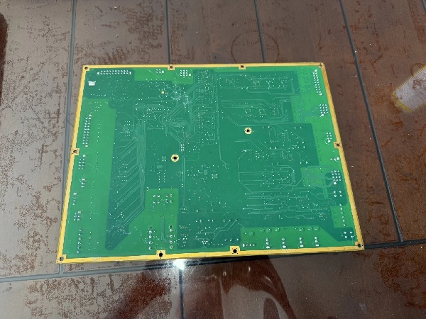
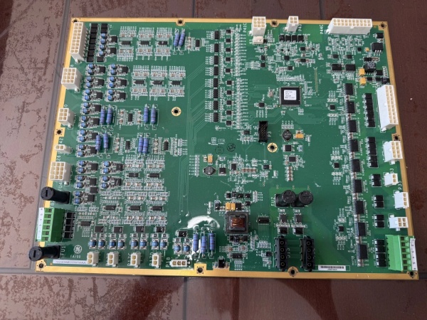
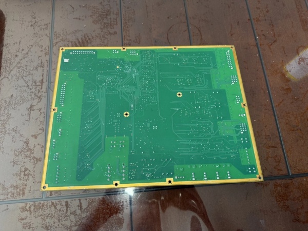
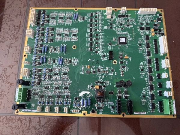
Hardware Architecture & Under-the-Hood Logic
The “PR2” suffix in this module denotes a specialized hardware build focusing on enhanced Power Regulation and component grading. Unlike standard WETC boards, the PR2 variant is heavily fortified with additional voltage regulation stages to support unstable auxiliary power sources.
- Localized Power Conditioning: The board integrates 44 voltage regulators, two coil inductors, and four strategically placed fuses. This dense power management network clamps down on electrical noise and guarantees that sensitive field devices (like proximity probes and thermocouples) receive perfectly stabilized 24VDC, even if the main turbine bus sags during motor startups.
- Aggressive Signal Conditioning: Raw 4-20mA loops and millivolt signals land on the two terminal strips. The onboard hardware applies low-pass filtering to strip out EMI from the generator exciter and yaw drives before the data ever reaches the processor.
- Edge Processing & Deterministic Routing: The processor scales sensor data locally and encapsulates it into Ethernet frames. The onboard switch prioritizes critical exciter control packets, preventing network storms from choking the system during a turbine trip event.
IS200WETCH1AAA
Field Service Pitfalls: What Rookies Get Wrong
Mistaking it for a Hot-Swappable VME Card
A technician assumes the IS200WETCH1APR2 is a standard rack card. He tries to force it into a VME rack slot without aligning it to the guide rails (which this board lacks). The gold-plated edge connector scrapes against the backplane, bending the delicate pins and destroying the conductive traces.
- Field Rule: This is a chassis-mounted or DIN-rail module, NOT a VME card. Never attempt to seat it in a rack. Secure it firmly to the mounting panel using the factory-drilled corner holes before connecting any wiring.
Compromising the Conformal Coating During Terminal Wiring
An installer is rushed and uses a powered screwdriver to tighten the terminal strip screws. The tool slips, gouging deep scratches into the board’s protective conformal coating. Over the next few months, moisture from the nacelle air condenses on the exposed fiberglass, causing a slow-forming dendritic short that eventually trips the safety chain.
- Quick Fix: Always use a manual screwdriver with a properly sized tip. Apply no more than 5 inch-pounds of torque to the terminal screws. If you scratch the coating, immediately touch it up with a brush-on acrylic conformal coating (like Humiseal 1B31) and allow a full 24-hour cure time before powering up.
Ignoring the Fuse Ratings During Power-Up
A mechanic replaces a blown fuse on the board with whatever 5A fast-blow fuse he finds in his truck, ignoring the fact that the original was a slow-blow, low-profile automotive-style fuse. When the turbine’s DC supply experiences a minor voltage spike, the incorrect fuse fails to absorb the surge, frying the onboard voltage regulators and taking the whole nacelle offline.
- Field Rule: GE selected specific fuses (located near the center and corners of the board) to protect the dense array of 44 voltage regulators. Always replace fuses with the exact OEM specified type and current rating. Check the ToolboxST logs for “Auxiliary Power Faults” before closing the breaker.
Commercial Availability & Pricing Note
Please note: The listed price is for reference only and is not binding. Final pricing and terms are subject to negotiation based on current market conditions and availability.


