
Description
Hard-Numbers: Technical Specifications
- Operating Voltage: 24 VDC (Nominal, 18-32VDC input range)
- Communication Protocols: Modbus TCP/IP, EGD (Ethernet Global Data), RNET
- Network Speed: 10/100 Mbps (Auto-negotiating Ethernet ports)
- Operating Temperature: -40°C to +70°C (Built for freezing nacelles and hot power plant floors)
- Isolation Rating: 1500 VDC (Galvanic isolation between field I/O and backplane logic)
- Physical Dimensions: 311 x 159 x 95 mm (L x W x H) / Approx. 12.25″ x 6.25″ x 3.75″
- Mounting Style: DIN Rail or Mark VIe Rack Mount
- Diagnostics: Front-panel LED array (Power, Link/Activity, Status, Fault)
- Humidity Tolerance: 5% to 95%, non-condensing
- Shock & Vibration: 15g shock, 0.05g RMS vibration resistance
IS200WETCH1AAA
The Real-World Problem It Solves
You are performing a major retrofit on an older wind farm. The original nacelle control electronics are failing due to moisture ingress and vibration fatigue. You need a direct replacement that not only fits the existing DIN rail cutout but also offers a higher Mean Time Between Failures (MTBF) to survive the harsh offshore environment. You need a module that can read dirty analog signals from aging vibration sensors, clean them up at the edge, and push them onto the RNET without causing broadcast storms.
Where you’ll typically find it:
- Wind Turbine Nacelle Top Boxes: Mounted on the DIN rail, directly interfacing with the generator exciter and yaw pitch motors.
- Offshore Platforms: Deployed in salt-spray environments where standard PCBs would corrode within months.
- Turbine Control Upgrades: Replacing legacy serial communication links with robust, deterministic Ethernet I/O.
It acts as the frontline defense against signal degradation, ensuring the main Mark VIe controller receives clean, actionable data even when the turbine is bucking in high winds.
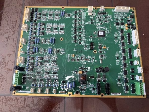
Hardware Architecture & Under-the-Hood Logic
This board is a further refinement of the WETC series, designed for maximum uptime in hostile environments. The “AAA” suffix denotes the highest hardware revision, featuring upgraded trace routing, enhanced conformal coating, and more robust power regulation components.
- Military-Grade Signal Conditioning: Raw 4-20mA loops and millivolt signals from thermocouples land on the terminal blocks. The board clamps inductive voltage spikes from contactors and applies aggressive hardware filtering to remove EMI from the generator exciter.
- Edge Processing & Buffering: The upgraded onboard processor handles complex scaling, limit-checking, and fast logic execution locally. This offloads the main controller, preventing it from choking on high-frequency interrupt requests during turbine start-up or shutdown.
- Deterministic Network Injection: The processed data is encapsulated into Ethernet frames and injected onto the RNET backbone. The onboard managed switch actively suppresses network storms and prioritizes critical exciter control packets to ensure deterministic delivery.
IS200WETCH1AAA
Field Service Pitfalls: What Rookies Get Wrong
Assuming Firmware Compatibility Across AAA, AA, and A Revisions
A technician swaps a fried H1A module with a brand-new H1AAA variant to get the turbine back online faster. He downloads the old configuration file without updating the ToolboxST project. The HMI throws a “Hardware ID Mismatch” error, and the new processor refuses to communicate, keeping the turbine parked.
- Field Rule: Never assume cross-revision compatibility. Always check the revision change log. Update the ToolboxST project to the latest service pack before downloading to an “AAA” revision board. Verify the firmware CRC matches the project requirements.
Damaging the Enhanced Conformal Coating During Installation
An installer is rushing to finish a nacelle retrofit. He strips the 24VDC power wires too long, and the excess bare copper shorts against the PCB when he tightens the terminal screw. The resulting spark burns through the AAA’s thick conformal coating, leaving the board vulnerable to future moisture ingress.
- Quick Fix: Use ferrules on all stranded wires entering the terminal blocks. Keep wire stripping precise—no more than 5/16 inch of exposed conductor. If you accidentally nick the conformal coating, touch it up immediately with a brush-on acrylic coating (like Humiseal 1B31) and let it cure for 12 hours.
Creating Ground Loops with Shielded Exciter Cables
An electrician grounds both ends of the shielded exciter cable—one end at the WETC module and the other at the exciter cabinet in the nacelle. The potential difference between the two grounds induces a current in the shield, which bleeds onto the signal wires. The HMI shows a constant 60Hz oscillation on the generator temperature readings.
- Field Rule: Ground the shield at the source (the sensor/exciter) and leave the shield floating at the WETC module end. Use a multimeter to check for continuity between the shield and the module ground terminal before closing the panel.
Commercial Availability & Pricing Note
Please note: The listed price is for reference only and is not binding. Final pricing and terms are subject to negotiation based on current market conditions and availability.


