
Description
Hard-Numbers: Technical Specifications
- Operating Voltage: 24 VDC (Nominal, 18-32VDC input range)
- Communication Protocols: Modbus TCP/IP, EGD (Ethernet Global Data), RNET
- Network Speed: 10/100 Mbps (Auto-negotiating Ethernet)
- Operating Temperature: -40°C to +70°C (Survives freezing nacelles and hot power plant floors)
- Isolation Rating: 1500 VDC (Galvanic isolation between field I/O and logic)
- Physical Dimensions: 311 x 159 x 95 mm (L x W x H) / Approx. 12.25″ x 6.25″ x 3.75″
- Mounting Style: DIN Rail or Mark VIe Rack Mount
- Diagnostics: Front-panel LED array (Power, Link/Activity, Status, Fault)
- Humidity Tolerance: 5% to 95%, non-condensing
- Shock & Vibration: 15g shock, 0.05g RMS vibration resistance
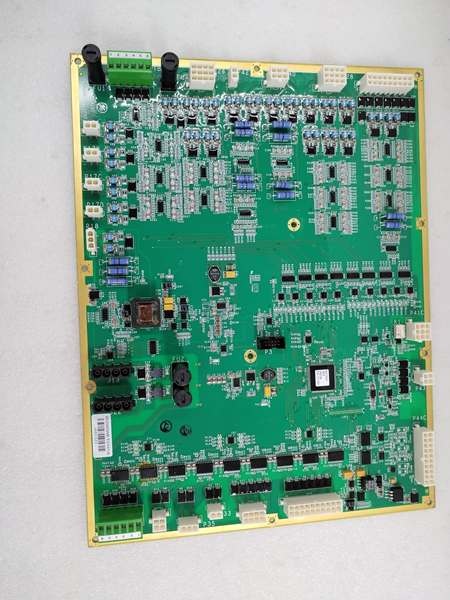
IS200WETCH1A
The Real-World Problem It Solves
You are troubleshooting a Mark VIe wind turbine system where the nacelle is taking a beating from freezing rain and violent gusts. The HMI is throwing intermittent “Exciter Comms Lost” and “Analog Input Out of Range” errors. The standard I/O cards in the main cabinet can’t filter the electrical noise from the generator brushes, and the humidity is causing track corrosion on older boards. You need a ruggedized, environmentally sealed interface module that can sit in the nacelle’s Top Box, withstand the moisture, and provide clean, deterministic data to the controller.
Where you’ll typically find it:
- Wind Turbine Nacelle Top Boxes: Mounted on the DIN rail, interfacing directly with vibration sensors, temperature probes, and exciter controls.
- Harsh Environment Skids: Deployed in offshore wind or coastal gas turbines where salt mist and condensation are constant threats.
- Turbine Control Retrofits: Upgrading legacy excitation control systems to modern, noise-immune Ethernet architectures.
It eliminates signal drift and corrosion-related failures by acting as a heavily protected, high-speed data aggregator in the most hostile parts of the turbine.
Hardware Architecture & Under-the-Hood Logic
This board is built to take a punch. Unlike standard PCBs, the “H1A” variant features a thick conformal coating that sheds moisture and resists corrosion from acidic or salty atmospheres. The “WETC” designation stands for Top Box Module C, meaning it’s designed to sit at the top of the turbine’s communication hierarchy.
- Aggressive Signal Conditioning: Raw 4-20mA loops and millivolt signals from thermocouples or vibration sensors land on the terminal blocks. The board uses hardware-level low-pass filters and transient voltage suppressors to clamp down on the massive EMI generated by the generator exciter and yaw motors.
- Local Processing & Buffering: The onboard processor scales the sensor data, performs limit checking, and buffers the results. This prevents the main Mark VIe controller from being bombarded with high-frequency, meaningless data.
- Deterministic Network Injection: The processed data is encapsulated into Ethernet frames and prioritized onto the RNET backbone. The onboard switch ensures that critical exciter control packets are delivered with deterministic timing, preventing network storms from choking the system during a turbine trip event.
IS200WETCH1A
Field Service Pitfalls: What Rookies Get Wrong
Ignoring the Conformal Coating During Repairs
A technician attempts to solder a new terminal block onto a WETC board inside a freezing nacelle. He melts the existing conformal coating, creating a conductive carbon path between two adjacent traces. When the turbine powers up, the short circuit causes a “Hardware Configuration Mismatch” error, taking the entire nacelle offline.
- Field Rule: Never apply excessive heat to a conformally coated board. If you must repair it, use a heat gun on low setting and reapply a high-quality silicone or acrylic conformal coating (like Humiseal 1B73) after the repair. Let it cure for 24 hours before reinstalling.
Improper Grounding of Shielded Exciter Cables
An electrician connects the braided shield of the exciter control cable to the WETC module’s ground terminal, and also grounds the other end of the shield at the exciter cabinet. Because the nacelle and the base tower have slightly different ground potentials, a ground loop forms. Stray currents induce a 60Hz hum on the signal wires, causing the HMI to display wildly fluctuating temperature and vibration readings.
- Quick Fix: Ground the shield at the source (the sensor/exciter) and leave the shield floating at the WETC module end. Use a multimeter to check for continuity between the shield and the module ground terminal before tightening the screws.
Forgetting to Update the I/O Database After Swapping Modules
A mechanic swaps a fried WETC module but grabs a generic spare from the truck instead of the project-specific replacement. He downloads the old configuration file without checking the hardware revision. The turbine throws a “Board ID Mismatch” error and refuses to boot, keeping the turbine in a locked-out state during peak wind hours.
- Field Rule: Always verify the exact part number and hardware revision (H1A, B, etc.) before swapping. If the revisions don’t match, update the ToolboxST project file to match the new hardware, or find the correct spare. Never guess.
Commercial Availability & Pricing Note
Please note: The listed price is for reference only and is not binding. Final pricing and terms are subject to negotiation based on current market conditions and availability.


