
Description
Hard-Numbers: Technical Specifications
- Operating Voltage: 24 VDC (Nominal, 18-32VDC input range)
- Communication Protocols: Modbus TCP/IP, EGD (Ethernet Global Data), RNET
- Network Speed: 10/100 Mbps (Auto-negotiating Ethernet ports)
- Operating Temperature: -40°C to +70°C (Withstands freezing nacelles and hot power plant floors)
- Isolation Rating: 1500 VDC (Galvanic isolation between field I/O and backplane logic)
- Physical Dimensions: 178 x 51 x 305 mm (L x W x H)
- Mounting Style: DIN Rail or Mark VIe Rack Mount
- Diagnostics: Front-panel LED array (Power, Link/Activity, Status, Fault)
- Humidity Tolerance: 5% to 95%, non-condensing
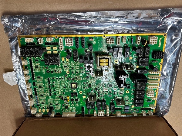
IS200WETBH1B
The Real-World Problem It Solves
You are troubleshooting a gas turbine package where the lube oil console is 300 feet from the main Mark VIe control room. Running hundreds of individual wires back to the main rack is causing massive voltage drops and signal noise. You need a ruggedized, localized I/O block that can sit on the DIN rail inside the harsh environment of the pump skid, filter out the electrical transients from the VFDs, and pipe clean, deterministic data back to the controller over a single redundant Ethernet cable.
Where you’ll typically find it:
- Remote Turbine Skids: Mounted on DIN rails in junction boxes for lube oil, fuel gas, or water injection systems.
- Wind Turbine Nacelles: Interfacing directly with pitch motors, yaw drives, and vibration sensors.
- Legacy Retrofits: Replacing outdated serial-linked I/O blocks to eliminate network bottlenecks.
It kills two birds with one stone: it drastically reduces your wiring headache by acting as a local I/O hub, and it protects your main control network from electrical noise by processing and buffering data at the edge.
Hardware Architecture & Under-the-Hood Logic
This board is a specialized edge processor. It doesn’t just pass data; it scrubs it clean before sending it to the controller. The “BAA” suffix indicates a specific hardware build, often tailored for enhanced MTBF in extreme conditions.
- Signal Acquisition & Conditioning: Raw 4-20mA analog loops and 24VDC discrete signals land on the terminal blocks. The board immediately clamps inductive voltage spikes (from relays or contactors) and applies hardware-level low-pass filtering to strip out high-frequency noise from nearby Variable Frequency Drives (VFDs).
- Local Processing & Buffering: The onboard processor handles fast logic execution and buffers the cleaned data. This offloads the main controller, preventing it from choking on high-frequency interrupt requests or irrelevant data.
- Deterministic Network Injection: The processed data is encapsulated into Ethernet frames and injected onto the RNET (Redundant Network). The onboard managed switch actively suppresses broadcast storms and prioritizes critical control packets to ensure deterministic delivery.
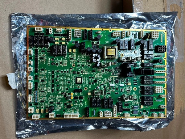
IS200WETBH1B
Field Service Pitfalls: What Rookies Get Wrong
Using the Module’s 24VDC as a Power Supply for Transmitters
A junior tech wires the 24VDC output from the WETB module directly to a bank of four 4-20mA pressure transmitters to save time. When the turbine starts, the inrush current from the transmitters overwhelms the module’s internal power regulator. The WETB browns out, dropping all local I/O and triggering a “Safety Chain Break” trip.
- Field Rule: The 24VDC terminals on this module are strictly for sinking/sourcing field device signals, not for powering them. Always use a separate, dedicated 24VDC power supply for your transmitters and sensors. Keep the module’s power feed strictly for its own logic.
Creating Ground Loops with Shielded Cables
An electrician connects the shielded cables of his analog sensors to the module’s ground terminal because he thought it looked like a good common ground. Since the turbine skid and the main control cabinet have slightly different ground potentials, a ground loop forms. The HMI starts showing jumpy, erratic readings on all analog inputs, especially when the main generator excites.
- Quick Fix: Run a heavy-gauge ground wire from the module’s chassis ground terminal directly to the skid’s primary earth ground. Never connect sensor cable shields to the module; ground them at the sensor end only to avoid potential differences.
Forgetting Network Termination in Daisy Chains
A contractor daisy-chains three WETB modules together using standard patch cables and leaves the termination switches in the default “OFF” position. The unterminated Ethernet lines act as antennas, picking up EMI from the 480VAC bus. Signal reflections cause massive packet loss, leading to “Network Storm” faults and a full turbine trip.
- Field Rule: For any linear daisy-chain network, the first and last nodes must have their 120-ohm termination enabled. Always verify the physical layer with a cable tester before powering up the rack.
Commercial Availability & Pricing Note
Please note: The listed price is for reference only and is not binding. Final pricing and terms are subject to negotiation based on current market conditions and availability.


