
Description
Hard-Numbers: Technical Specifications
- Operating Voltage: 24 VDC (Nominal, range 18-32VDC)
- Communication Protocols: Modbus TCP/IP, EGD (Ethernet Global Data), RNET
- Network Speed: 10/100 Mbps (Auto-negotiating Ethernet)
- Operating Temperature: -40°C to +70°C
- Isolation Rating: 1500 VDC (Galvanic isolation between I/O and logic)
- Physical Dimensions: 178 x 51 x 305 mm (L x W x H)
- Mounting Style: DIN Rail or Mark VIe Rack Mount
- Diagnostic LEDs: Link/Activity, Status, Fault, Collision
- Humidity Tolerance: 5% to 95%, non-condensing
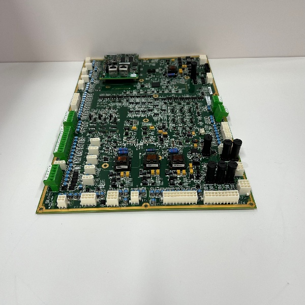
GE IS200WETAH1BB
The Real-World Problem It Solves
You are debugging a Mark VIe wind turbine system during a thunderstorm. The nacelle is swaying violently, and the HMI is spamming “Pitch Position Lost” and “Network Storm” alarms because the unshielded, daisy-chained sensors can’t handle the electrical noise from the lightning strikes. You need a hardened, localized I/O block that can aggregate the nacelle’s temperature, pressure, and proximity sensors, scrub the signal noise, and feed deterministic data to the main controller over a redundant Ethernet link.
Where you’ll typically find it:
- Wind Turbine Nacelle Control Cabinets: Mounted on the DIN rail, interfacing directly with pitch motors, yaw drives, and vibration sensors.
- Offshore Wind Farms: Surviving constant salt mist and extreme temperature swings where standard network switches fail.
- Turbine Control Retrofits: Upgrading legacy serial-linked I/O to modern, high-speed Ethernet architectures.
It eliminates noisy signal transmission and single-point-of-failure network drops by acting as a rugged, deterministic I/O and networking pit stop in the harshest parts of the turbine.
Hardware Architecture & Under-the-Hood Logic
This board is a dual-threat workhorse. It doesn’t just pass data; it conditions it. Located on the DIN rail in the nacelle, it serves as the bridge between the brutal physical environment and the pristine Mark VIe backplane. The “BB” suffix indicates a specific hardware build, often featuring upgraded passive components or firmware optimizations for enhanced MTBF in mission-critical deployments.
- Signal Acquisition & Conditioning: Raw analog (4-20mA) and digital signals from local nacelle devices land on the terminal blocks. The board filters out electrical transients caused by the generator’s excitation system and vibration-induced chatter.
- Local Processing & Buffering: It processes the clean signals locally, applying logic and buffering the data to prevent the main controller from being overwhelmed by high-frequency interrupts.
- Network Injection & Redundancy: The processed data is encapsulated into Ethernet frames. The onboard switch then routes this traffic to the RNET (Redundant Network), ensuring that even if one Ethernet cable is severed by falling ice, the data still reaches the controller via the redundant path.
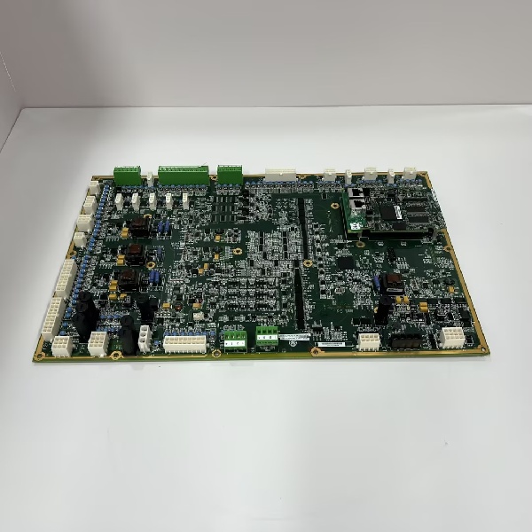
GE IS200WETAH1BB
Field Service Pitfalls: What Rookies Get Wrong
Omitting the 120-Ohm Termination Resistor on Modbus Legs
A junior tech commissions a new pitch motor drive connected to the ETA module via Modbus RS-485. He forgets to install the 120-ohm terminating resistor at the farthest device on the daisy chain. During a high-wind event, the unterminated line acts as an antenna, picking up EMI from the 480VAC bus. The reflected signal causes massive data corruption, resulting in a “CRC Mismatch” fault and an emergency full-feather trip.
- Field Rule: Always measure the resistance across the Modbus pair with a calibrated multimeter. You must read exactly 120 ohms (or 60 ohms if the network is terminated at both ends). No resistor means no reliable data in a turbine.
Using Commercial-Grade RJ45 Connectors in the Nacelle
An electrician uses standard office-grade RJ45 connectors with no strain relief to land the RNET cables into the ETA board. Three weeks later, the constant low-frequency vibration from the gearbox loosens the crimped pins. The link drops intermittently, causing the Mark VIe system to log “Network Storm” errors and eventually trip the turbine on “Communications Loss.”
- Quick Fix: Never use commercial connectors in rotating or vibrating machinery. Use industrial-grade, shielded RJ45s with metal housings and strain-relief boots. After crimping, apply a small dab of blue Loctite or RTV silicone to the locking tab to prevent it from vibrating loose.
Creating IP Address Conflicts on the Turbine Network
A mechanic swaps out a faulty ETA board and blindly downloads the configuration from the last guy’s laptop without verifying the static IP address. The new board boots up with a duplicate IP address already in use by the vibration monitoring system. This creates an IP conflict that crashes the entire turbine control network segment.
- Field Rule: Before powering up a replaced board, verify its intended IP address against the network topology diagram. Ping the address from the HMI. If you get a reply, that IP is already taken. Change it in the Toolbox software before mounting it in the rack.
Commercial Availability & Pricing Note
Please note: The listed price is for reference only and is not binding. Final pricing and terms are subject to negotiation based on current market conditions and availability.


