
Description
Hard-Numbers: Technical Specifications
- Number of Channels: 8 vibration input channels
- Input Type: ICP/IEPE accelerometer (4 mA constant current source)
- Input Voltage Range: ±10 V peak (for ICP sensors)
- Current Source: 4 mA typical (2-20 mA configurable)
- Frequency Range: 0.5 Hz to 20 kHz (software programmable filter)
- Sampling Rate: 100 kHz maximum per channel
- Resolution: 16-bit ADC (up to ±0.015% full scale)
- Input Sensitivity: 10-100 mV/g typical (programmable gain: 0.1-100 V/g)
- Dynamic Range: 80 dB typical
- Common Mode Rejection: 60 dB typical at 60 Hz
- Isolation: 1500V RMS between channels and backplane
- Module Power Draw: 2.8A @ 5VDC from backplane
- Backplane Current: 5V: 2.8A max
- Operating Temperature: -20°C to 70°C (-4°F to 158°F)
- Storage Temperature: -40°C to 85°C (-40°F to 185°F)
- LED Indicators: PWR, OK, FAULT, individual channel status LEDs
- Cooling: Forced air (requires Mark VIe backplane cooling)
- Module Slot: Mark VIe I/O backplane (any slot in expansion rack)
- Communication: Backplane via TCP/IP (embedded vibration processor)
- Firmware Version: Compatible with Mark VIe v6.0 and later
- Alarm Thresholds: Configurable per channel (overall, 1x RPM, harmonics)

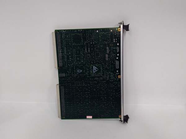
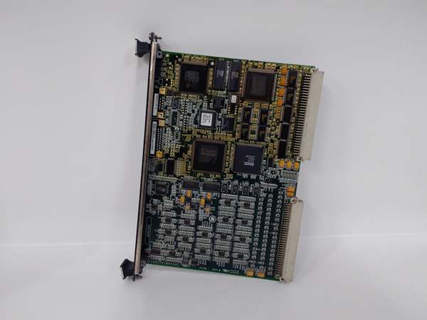
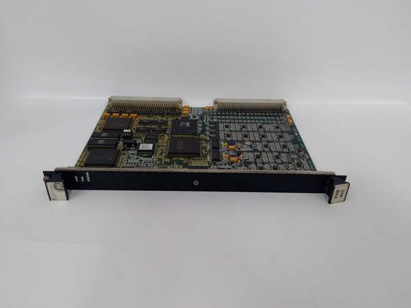
GE IS200VVIBH1C
The Real-World Problem It Solves
Turbine bearings degrade over time, and vibration is the early warning sign. The IS200VVIBH1C provides 8 channels of high-speed vibration measurement with programmable filtering for frequency band analysis. This data enables predictive maintenance and early detection of bearing wear, rotor unbalance, and gear mesh issues.
Where you’ll typically find it:
- Gas turbine bearing health monitoring systems
- Steam turbine vibration monitoring packages
- Compressor packages with critical bearing protection
Bottom line: It gives you multi-channel vibration measurement for predictive maintenance and machinery protection.
Hardware Architecture & Under-the-Hood Logic
The IS200VVIBH1C is a dedicated vibration input module for Mark VIe turbine control racks. Each of the 8 channels has dedicated signal conditioning, constant current source (for ICP/IEPE accelerometers), anti-aliasing filters, and a 16-bit ADC. The module supports programmable gain (0.1-100 V/g) to accommodate various accelerometer sensitivities. An embedded ARM processor manages channel configuration, FFT (Fast Fourier Transform) analysis, and backplane communication. Sampling parameters (rate, filter, gain) are configured via Mark VIe software and stored in non-volatile memory. The firmware includes real-time FFT analysis for frequency band isolation, enabling detection of specific fault frequencies (1x RPM, 2x RPM, gear mesh, bearing defects). Vibration data (overall RMS, frequency spectrum, waveform) is transmitted to the main controller via backplane TCP/IP at 10 Hz update rate for trending. Alarm logic evaluates overall vibration levels and frequency band values against configurable thresholds.
Internal signal flow:
- ICP accelerometer output arrives at terminal block
- Module supplies 4 mA constant current source to power accelerometer
- Signal passes through AC coupling and protection circuits
- Programmable gain amplifier adjusts signal based on sensitivity setting
- Anti-aliasing filter (low-pass) removes frequencies above Nyquist
- Sample-and-hold circuit freezes voltage at specified sampling rate
- 16-bit ADC converts analog signal to digital value
- Digital data is transferred to channel buffer
- Embedded processor calculates RMS value and performs FFT analysis
- Frequency bands (1x RPM, harmonics, bearing bands) are extracted
- Processor formats vibration data into Ethernet packets
- Data transmitted to main controller via backplane TCP/IP
- Alarm logic evaluates levels against thresholds; alarms generated if exceeded
GE IS200VVIBH1C
Field Service Pitfalls: What Rookies Get Wrong
Incorrect accelerometer sensitivity causes scaling errorsICP accelerometers have varying sensitivity values (10-100 mV/g). I’ve seen technicians install a new accelerometer with different sensitivity but leave the module configuration unchanged, resulting in vibration readings that are 10x off.
- Field Rule: Always verify the accelerometer’s sensitivity value from the nameplate or data sheet. Enter the exact sensitivity (mV/g) into the IS200VVIBH1C channel configuration in Mark VIe software. Test the channel with a calibrated vibration shaker if available. Verify RMS readings match expected levels during commissioning.
Using wrong current source settings damages accelerometersThe module supplies constant current to power ICP sensors. I’ve seen technicians configure 20 mA for a 4 mA accelerometer, overheating and destroying the internal electronics.
- Field Rule: Check the accelerometer’s current rating before configuring the channel. Most ICP accelerometers require 2-4 mA. Set the module current source accordingly in Mark VIe software. Never exceed the accelerometer’s maximum current rating (typically 20 mA absolute maximum). Measure accelerometer output voltage with a multimeter—should be between 5-12 VDC during normal operation.
Ignoring cable capacitance causes signal attenuationICP sensor cables have capacitance that affects high-frequency response. I’ve seen technicians use 100-meter cable without compensating for capacitance, resulting in attenuation above 10 kHz and missed high-frequency vibration data.
- Field Rule: Keep sensor cable lengths under 30 meters (100 feet) for full frequency response. Use low-capacitance cable specifically designed for ICP sensors (typically <30 pF/ft). If long runs are unavoidable, compensate for capacitance in Mark VIe channel configuration or use line drivers. Document cable type and length in your installation records.
Leaving channels unpowered creates false alarmsThe constant current source must be enabled for each used channel. I’ve seen technicians leave the current source disabled, causing the input to float and trigger false loss-of-signal alarms.
- Field Rule: Enable the constant current source for all channels with connected accelerometers. In Mark VIe software, verify the current source parameter is set to 4 mA (or the correct value for your accelerometer). Disable the current source only for unused channels—never leave enabled channels with open circuit.
Forgetting to configure frequency filters masks faultsVibration faults manifest at specific frequencies (1x RPM, bearing defects, gear mesh). I’ve seen technicians use default settings that include all frequencies, masking specific fault signatures with broadband noise.
- Field Rule: Configure frequency filters based on your machinery characteristics. For unbalance detection, use bandpass around 1x RPM (±10%). For bearing defects, enable high-frequency band (>5 kHz). For gear mesh, configure narrow bands around gear mesh frequencies. Document filter settings in your vibration analysis procedure.
Improper grounding creates 60 Hz noiseICP sensors are sensitive to ground loops and common mode noise. I’ve seen vibration readings with 60 Hz hum and elevated broadband levels because technicians tied the shield to ground at both ends.
- Field Rule: Use shielded twisted pair cable for all ICP sensor wiring. Terminate the shield at the module end only—never at both ends. Ensure the module chassis is bonded to the cabinet ground via the PE terminal. Measure ground potential difference between sensor ground and module ground—should be less than 1VAC. If 60 Hz noise persists, consider using differential accelerometers.
Not trending vibration data leads to missed warningsSingle-point vibration measurements are less valuable than trends. I’ve seen operators check only the current reading without historical context, missing gradual increases that indicate impending failure.
- Field Rule: Enable data logging for all critical vibration channels in the Mark VIe historian. Review trends weekly and look for gradual increases (0.5x over 3 months is a warning sign). Set pre-alarm thresholds at 50% of trip level to provide early warning. Document trend analysis in your predictive maintenance program.
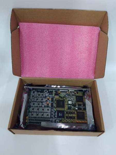
Commercial Availability & Pricing Note
Please note: The listed price is for reference only and is not binding. Final pricing and terms are subject to negotiation based to current market conditions and availability.


