

Description
Hard-Numbers: Technical Specifications
- Valve Type: Electro-hydraulic servo valve (2-coil, differential or single-coil)
- Output Current Range: 0-40 mA per coil, ±20 mA differential
- Current Resolution: 12-bit (0.01 mA step size)
- Current Loop Update Rate: 1 kHz typical (configurable 100 Hz-2 kHz)
- Coil Resistance: 10-100 Ω typical (auto-sensing for common valve types)
- Coil Inductance: 0.1-1.0 H typical
- Output Voltage Compliance: ±24 VDC max per coil
- Isolation: 1500V RMS between valve outputs and backplane
- Feedback Type: Valve position feedback via 4-20 mA, 0-10 V, or resolver
- Position Loop Bandwidth: 10 Hz typical (adjustable for valve response)
- Module Power Draw: 3.5A @ 5VDC from backplane
- Backplane Current: 5V: 3.5A max
- Operating Temperature: -20°C to 70°C (-4°F to 158°F)
- Storage Temperature: -40°C to 85°C (-40°F to 185°F)
- LED Indicators: PWR, OK, FAULT, COIL A, COIL B, POS (position feedback status)
- Cooling: Forced air (requires Mark VIe backplane cooling fan)
- Module Slot: Mark VIe I/O backplane (any slot in expansion rack)
- Communication: Backplane via TCP/IP (embedded valve driver processor)
- Firmware Version: Compatible with Mark VIe v5.0 and later
- Fault Response: Fail-safe valve closure on fault (configurable spring-return mode)

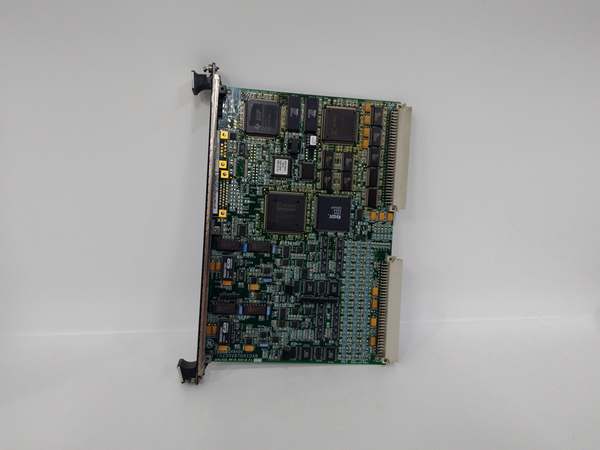
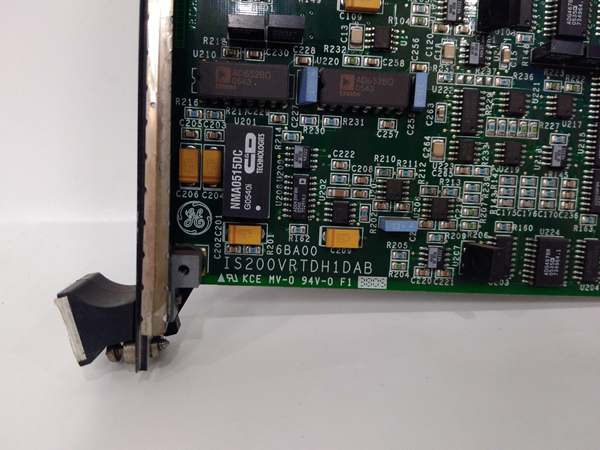
GE IS200VRTDH1D
The Real-World Problem It Solves
Servo valves need precise current control for accurate positioning. The IS200VRTDH1D delivers closed-loop current control at 1 kHz update rates, ensuring your fuel and steam valves respond quickly to load changes. This module is critical for maintaining stable turbine speed and load control.
Where you’ll typically find it:
- Gas turbine fuel valve control cabinets (gas fuel valves)
- Steam turbine governor valve control systems (steam admission valves)
- Combined cycle plant control racks with hydraulic actuation requirements
Bottom line: It gives you precise servo valve actuation for critical turbine control applications.
Hardware Architecture & Under-the-Hood Logic
The IS200VRTDH1D is a dedicated servo valve driver module for Mark VIe control racks. It includes dual current output stages for driving servo valve coils. Each coil has its own current loop controller running at 1 kHz, with current feedback from Hall effect sensors ensuring accurate output current regulation. The module also processes valve position feedback from an external LVDT or resolver, closing the position loop internally. An embedded ARM processor manages valve characterization, auto-tuning, and backplane communication. The firmware includes adaptive filtering for hydraulic vibration and hydraulic resonance rejection, reducing valve dither and improving positioning accuracy. The fault response logic provides fail-safe operation—on detection of a fault (loss of position feedback, coil open circuit, or coil short circuit), the module drives valves to the safe position (typically closed) and reports the fault to the main controller.
Internal signal flow:
- Main controller sends valve position command via backplane TCP/IP
- Embedded processor calculates required coil currents based on valve characterization
- Position feedback (LVDT/resolver) provides actual valve position
- Position error is calculated and fed to current loop controller
- Current loop controller generates PWM duty cycle for each coil
- Coil drivers amplify PWM to produce 0-40 mA current output
- Hall effect current sensors measure actual coil currents
- Current feedback is compared to command; error drives PI controller
- Output currents drive servo valve coils to achieve commanded position
- Position loop updates at 10 Hz bandwidth for closed-loop valve control
- Fault detection circuits monitor coils and position feedback continuously
- On fault detection, failsafe logic drives coils to safe position (spring-return or closed)
GE IS200VRTDH1D
Field Service Pitfalls: What Rookies Get Wrong
Mismatching coil resistance and inductance causes oscillationEach servo valve has specific coil parameters. I’ve seen technicians install a new valve without updating coil resistance and inductance parameters, causing the current loop to become unstable and the valve to oscillate.
- Field Rule: Always measure coil resistance with a multimeter before connecting to the IS200VRTDH1D. Record resistance values and enter them into the Mark VIe valve configuration. If the valve is OEM-specified, use the recommended values from the valve data sheet. Perform autotune after any valve replacement to calibrate the current loop.
Leaving position feedback disconnected causes unstable operationThe VTRD module requires position feedback for closed-loop control. I’ve seen technicians commission valves with LVDT feedback disconnected, causing the valve to drift or hunt because the module can’t see actual position.
- Field Rule: Verify LVDT or resolver connection to the module before energizing. Test position feedback by manually moving the valve stem—observe the POS LED and verify position reading in Mark VIe software. If feedback shows 0% or 100% constant with valve movement, check the feedback connection and configuration. Never operate a servo valve without position feedback unless configured for open-loop current mode (rare in turbine applications).
Incorrect wiring of differential coils causes torque fightMany turbine valves use differential coil configuration for safety. I’ve seen technicians wire both coils in parallel instead of differential, reducing torque output and causing unstable valve behavior.
- Field Rule: Confirm the valve’s coil configuration (single-coil or differential). For differential valves, coil A is the driving coil and coil B is the spring-return bias coil. Configure the module accordingly in Mark VIe software. Verify coil wiring with a multimeter: differential coils should show opposite polarity output during normal operation.
Overlooking failsafe testing leads to unexpected shutdownsThe failsafe response is critical for turbine safety. I’ve seen plants trip because the failsafe mode wasn’t tested during commissioning, and on a fault, the valve drove to the wrong position.
- Field Rule: Test failsafe response during commissioning and annually thereafter. Simulate a fault by disconnecting position feedback or a coil wire. Verify the valve moves to the safe position (closed for fuel valves, open for governor valves). Document failsafe direction and timing. Configure the module to trip the turbine on failsafe if required by your application.
Ignoring hydraulic resonance causes valve wearHydraulic systems have resonant frequencies that can cause valve chatter. I’ve seen operators run valves at resonant frequencies without enabling adaptive filtering, leading to accelerated wear and premature valve failure.
- Field Rule: Identify hydraulic resonant frequencies during commissioning. Enable adaptive filtering (notch filters) in the module configuration to suppress resonance. Monitor valve vibration with a portable analyzer during startup. Adjust filter frequency if resonance shifts over time due to system changes (new piping, pressure changes).
Not monitoring coil temperature leads to insulation failureServo valve coils generate heat during continuous operation. I’ve seen technicians ignore coil temperature warnings, resulting in coil short circuits and valve replacement.
- Field Rule: Monitor coil resistance for temperature changes. A 10% increase in resistance indicates coil overheating (typical for Class H insulation at 180°C). Reduce coil current if possible, or check hydraulic oil temperature. Install an external temperature sensor if available for high-duty applications. Record coil resistance trends during maintenance inspections.
Commercial Availability & Pricing Note
Please note: The listed price is for reference only and is not binding. Final pricing and terms are subject to negotiation based to current market conditions and availability.


