
Description
Product Introduction
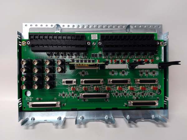
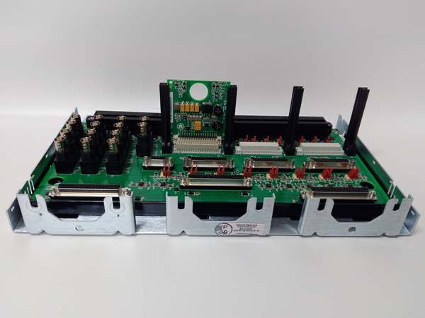
The GE is a vibration terminal board designed as the field interface for Mark VIe turbine controls, bridging high-impedance proximity probes to the VVIB processor. It handles the raw millivolt signals from shaft sensors, applying passive filtering and bias voltage (-24 V DC) before the data hits the backplane.
This “H2ACC” revision includes conformal coating (C-suffix) and improved noise rejection over H1A variants. It supports 8 independent channels, typically mapped to radial vibration and thrust position probes. Signal bandwidth covers 0.5 Hz to 10 kHz, capturing transient rotor events like rubs or oil whirl with 16-bit precision .
IS200TVBAH2ACC
Key Technical Specifications
- System Role: TVBA Terminal Board (Vibration/Position Inputs)
- Input Channels: 8 Independent (Configurable via ToolboxST)
- Sensor Type: Eddy Current Proximity Probes (e.g., Bently Nevada 3300)
- Signal Range: -24 V DC to 0 V DC (Typical Bias + AC Ripple)
- Input Impedance: > 1 MΩ (High-Z to prevent probe loading)
- Bandwidth: 0.5 Hz to 10 kHz (Configurable Filters)
- Resolution: 16-Bit ADC (On VVIB Processor, conditioned here)
- Bias Supply: -24 V DC (Internally generated or External)
- Connectors: Pluggable Terminals (Field), 50-pin D-Sub (To VVIB)
- Coating: Conformal Coated (ACC Revision)
- Temp Range: -30 °C to +65 °C (Operational)
- Isolation: Channel-to-Ground / Backplane
Quality Control Process (Engineer’s Perspective)
- Incoming Verification: Match the GE serial to the manifest. Inspect the pluggable terminal blocks for cracked plastic levers—common after removal. Check the conformal coating near the coaxial inputs for carbon tracking.
- Live Functional Test: Rig with a VVIB simulator. Inject a -10 V DC offset + 100 mV AC (simulating probe gap). We scope the output to the processor; THD shouldn’t exceed 3% across the 10 kHz band.
- Electrical Parameter Test: Back-probe the -24 V DC bias with a Fluke 115. Megger the probe terminals to chassis at 500 V; leakage must hold >10 MΩ to survive shaft currents.
- Jumper Verification: Photograph the bias enable jumpers (if applicable). Forgetting to enable “-24V Bias” leaves the proximity probe unpowered—well, technically some configs use external power, but the jumper must match the PIB setup.
- Final QC & Packaging: Torque test a terminal screw (0.5 Nm). Bag in rigid ESD foam. Label “QC Passed – Bias/Signal Verified” with the date.
Replacement Pitfall Guide
❗ Bias Voltage (Critical): The GE supplies -24 V DC to power the probe loop. Forgetting to set the “Bias Enable” jumper (or soft-config) results in 0 V DC at the terminal, causing “Probe Failed” alarms and preventing gap voltage measurement.
❗ H1A vs H2A Compatibility: This is an H2 revision. Mixing it with H1A boards in a TMR triplet causes “Hardware Mismatch” votes. All three (A, B, C) racks must use H2ACC for consistency.
❗ Shield Grounding: Probe shields terminate at the single-point ground lug on the terminal block, not the DIN rail. Grounding at the probe andthe terminal creates a ground loop, injecting 60 Hz hum that masks sub-micron vibration.
❗ Coating (ACC): The “ACC” suffix means heavy conformal coat. Swapping with a bare “A” unit in a steam turbine bay leads to creepage faults on the high-Z inputs within months due to condensation.
❗ ESD to Connectors: The 50-pin header goes to VVIB. Discharge to the panel frame before unplugging—static in dry turbine halls (common in northern China winters) fries the input buffers instantly.
Keep these in mind and you’ll cut 90% of rework time.
IS200TVBAH2ACC
Compatibility Matrix & Benchmarks
- GE → GE IS200TVBAH1A : Needs Adaptation — H2 has different filter components; verify TMR triplet uniformity.
- GE → GE IS200VVIB (Processor) : Direct — Physical mate for the Vibration Processor.
- GE → Standard Analog Input : Incompatible — Handles specific -24V bias and probe drive currents.
- Sampling Rate: Up to 10 kHz (Per channel, dynamic)
- Bias Stability: -24 V DC ± 1 V (Loaded)
- Accuracy: ±0.5% Full Scale (Typical, verify with OEM datasheet)


