
Description
Product Introduction
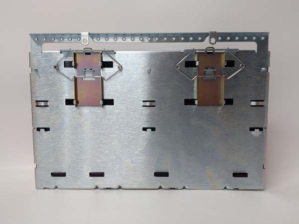
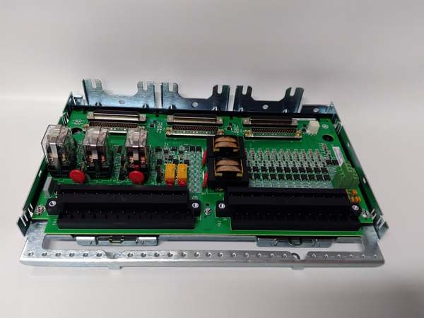
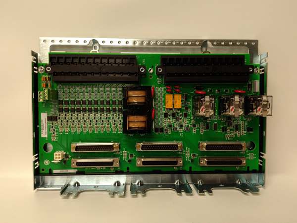
The GE is a turbine terminal board designed to interface magnetic speed pickups (proximity probes) with the TTUR or TTRH I/O processor in Mark VIe systems. It handles the raw sine waves from shaft sensors, cleaning them up for the 24-bit counters on the processor side.
This “CFD” revision includes a thick conformal coating for corrosion resistance in turbine bays. It supports six independent channels covering 1 Hz to 20 kHz. The input sensitivity sits at 1.5 Vpp minimum—well, technically it handles passive VR pickups best, but active sensors work with jumper changes .
IS200TTURH1CFD
Key Technical Specifications
- System Role: TTUR Terminal Board (Speed Inputs)
- Input Channels: 6 Independent (Configurable for Mag Pickup / Proximitor)
- Signal Type: Sine Wave (Passive VR) / DC Pulse (Active)
- Frequency Range: 1 Hz to 20 kHz (Configurable via ToolboxST)
- Input Sensitivity: 1.5 Vpp (Minimum Trigger Threshold)
- Input Impedance: > 10 kΩ per channel
- Resolution: 24-Bit Time-Stamp Counter (On Processor)
- Isolation: 500 V AC (Channel-to-Channel / Channel-to-Logic)
- Logic Power: 24 Vdc / 28 Vdc (From I/O Pack Backplane)
- Connectors: Pluggable Euro-Style Terminal Blocks (Field), 50-pin D-Sub (To Pack)
- Coating: Conformal Coated (CFD Suffix)
- Temp Range: -30 °C to +65 °C (Operational)
Quality Control Process (Engineer’s Perspective)
- Incoming Verification: Match the serial on the GE to the manifest. Inspect the terminal blocks for cracked plastic—common after removal. Check the conformal coating for flaking near the high-voltage traces.
- Live Functional Test: Rig with a TTRH simulator. Inject a 5 kHz sine wave (simulating shaft spin). We scope the terminal outputs; signal distortion shouldn’t exceed 5% THD at 1.5 Vpp input.
- Electrical Parameter Test: Back-probe the 24 Vdc input with a Fluke 115. Megger the sensor terminals to chassis at 500 V; leakage must hold >10 MΩ to survive shaft grounding currents.
- Jumper Verification: Photograph the configuration jumpers (if present) for sensor type. Forgetting a “Passive/Active” strap mismatch inverts the speed reading—though your mileage may vary on units using soft-config only.
- Final QC & Packaging: Torque test a spare terminal screw to check clamp tension. Bag in rigid ESD foam. Label “QC Passed – Signal Conditioning OK” with the date.
Replacement Pitfall Guide
❗ Sensor Type (Passive vs Active): The GE expects Passive (Magnetic/VAR) pickups by default. Landing an Active (Proximitor/DC) sensor without changing the jumper (or software config) results in “Speed Loss” alarms at zero RPM.
❗ Terminal Polarity: Speed inputs (A/B terminals) are polarity sensitive. Swapping the shield and signal wire flips the sine wave phase, causing the counter to miss pulses or read negative speed during run-up.
❗ Coating Thickness: This is a “CFD” (Coated) unit. Swapping it for a bare “C” revision in a steam-turbine bypass cabinet leads to creepage faults on the input buffers within 12 months due to humidity.
❗ Shield Grounding: The cable shield drains on the specific lug (usually TB1). Grounding the shield at the junction box andthe terminal board creates a ground loop, injecting 60 Hz hum that masks the low-amplitude pickup signal at low speed.
❗ ESD to Connectors: The 50-pin header goes to the processor. Discharge to the panel frame before unplugging—critical in dry turbine halls (common in northern China winters).
Keep these in mind and you’ll cut 90% of rework time.
IS200TTURH1CFD
Compatibility Matrix & Benchmarks
- GE → GE IS200TTURH1C : Direct — CFD is coated revision; verify jumper settings match site config.
- GE → GE IS200TTRH (Processor) : Direct — Physical mate for the Speed I/O Pack.
- GE → Standard Terminal Block : Incompatible — Handles specific VR sensor biasing and filtering.
- Speed Accuracy: ±0.01% (Reading, stable temp)
- Input Range: 1 Hz – 20 kHz (Verify with OEM datasheet)
- Isolation Test: 500 V AC (Channel to Logic, 1 min)


