
Description
Product Introduction
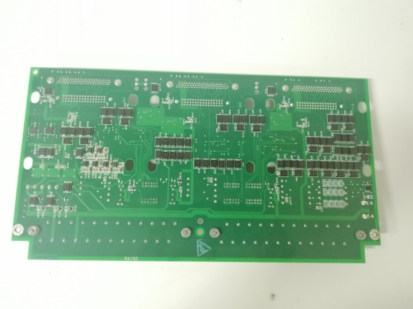
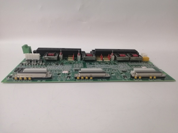
The GE is a servo terminal board acting as the field interface for Mark VIe turbine controls, bridging the gap between the PSVO processor and hydraulic servo valves. It handles the heavy lifting of driving valve coils and conditioning feedback from LVDTs to ensure the fuel stroke reference stays on target.
This “H1A” revision supports two independent control channels, each driving a servo valve and reading up to four LVDTs for position verification. It features conformal coating for corrosion resistance. Response latency from processor command to valve movement typically sits under 5 ms in closed-loop mode .
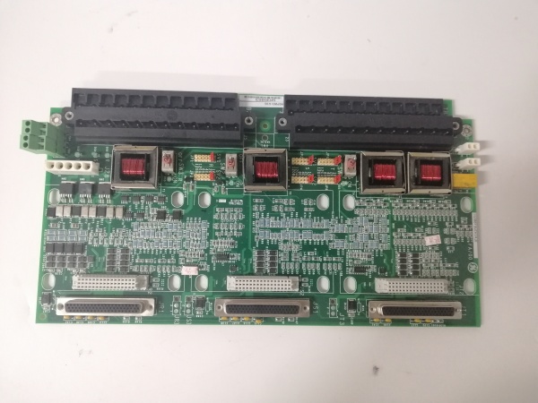
GE IS200TSVCH1A
Key Technical Specifications
- System Role: TSVC Terminal Board (Servo I/O)
- Channels: 2 Independent (Valve A & Valve B)
- Servo Outputs: 2 (Bi-directional current, jumper select 10-120 mA)
- LVDT Inputs: 8 Windings (Supports 1-4 LVDTs per channel)
- LVDT Excitation: 2 Sources (Isolated + Non-Isolated options via jumpers)
- Pulse Inputs: 2 (Magnetic or TTL, for flow/speed monitoring)
- Logic Power: 24 Vdc / 28 Vdc (Via Backplane/J28)
- Power Draw: ~10 W (Typical, verify with OEM datasheet)
- Coating: Conformal Coated (Standard for H1A)
- Temp Range: -30 °C to +65 °C (Operational)
- Connectors: 2x 50-pin Ribbon (To PSVO), Barrier Strips (Field)
Quality Control Process (Engineer’s Perspective)
- Incoming Verification: Match the serial on the GE to the manifest. Inspect the barrier terminal blocks for corroded screws—common in coastal plants. Check the 50-pin headers for bent pins; forced insertion cracks the PCB traces.
- Live Functional Test: Rig with a PSVO simulator. Drive the servo outputs across 0-100% stroke. We scope the output current; ripple shouldn’t exceed 50 mV p-p at 20 mA drive—excessive noise means the filter caps are drying out.
- Electrical Parameter Test: Back-probe the 24 Vdc input with a Fluke 115. Megger the servo outputs to chassis at 500 V; leakage must hold >10 MΩ to survive valve coil transients.
- Jumper Verification: Photograph the configuration jumpers (JP1-JP6 for coil current). A wrong strap (e.g., 40 mA setting on a 120 mA valve) saturates the output transistor—well, technically the PSVO software limits it, but hardware limits are the last line of defense.
- Final QC & Packaging: Exercise the screw terminals with a screwdriver to check clamp tension. Bag in static foam. Label “QC Passed – Loopback Verified” with the date.
Replacement Pitfall Guide
❗ Jumper Mismatch: The GE uses JP1-JP6 to set servo current (10/20/40/80/120 mA). Forgetting to match these to the newvalve specs (e.g., leaving old 40 mA jumpers for a 120 mA valve) limits stroke and causes “Servo Current Limit” faults.
❗ LVDT Phasing: Terminals JFS/JGS (LVDT secondary) are polarity sensitive. Swapping the “Pos+” and “Pos-” wires flips the feedback sign, causing the valve to slam full open thinking it’s closed—check the wiring diagram twice.
❗ Shield Grounding: The shield drain wire lands on the specific ground lug (usually left of TB). Grounding the shield at the valve andthe terminal board creates a ground loop, injecting 60 Hz hum into the LVDT signal.
❗ PSVO Compatibility: This board is for PSVO packs. Do not force it into a VSVO (simplex) slot; the backplane pinout differs and you’ll back-feed 28 Vdc into a sense line, cooking the processor.
❗ ESD to Headers: The 50-pin ribbons go to the processor. Discharge to the panel frame before unplugging—though your mileage may vary on cabinet grounding in older turbine halls.
Keep these in mind and you’ll cut 90% of rework time.
GE IS200TSVCH1A
Compatibility Matrix & Benchmarks
- GE → GE IS200TSVCH2A : Needs Adaptation — H2A may support different I/O counts; verify jumper map.
- GE → GE IS200TSVO (PSVO) : Direct — Primary mate for the Servo Processor.
- GE → Standard Analog Output : Incompatible — Handles high-current servo loops, not 4-20 mA instrumentation.
- Servo Response: < 5 ms (Command to Current Stable)
- LVDT Accuracy: ±0.1% F.S. (With proper excitation setup)
- Isolation Test: 500 V AC (Field to Logic, verify with OEM datasheet)


