
Description
Product Introduction
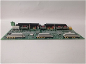
The GE is a primary trip terminal board serving as the field interface for Mark VI turbine controls, connecting pulse rate sensors and E-Stop circuits to the PTUR or YTUR I/O packs. It handles the raw voltage signals that determine if the turbine is overspeeding or requires an emergency shutdown.
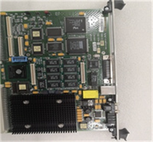
This “H2AHE” revision includes specific conformal coating (implied by suffix variations) and supports voltage detection inputs up to 140 Vdc. It processes signals from three redundant (TMR) sections, ensuring a voted trip occurs even if one processor falters. Response latency from signal spike to output relay is typically under 5 ms .
IS200TRPAH2AHE
Key Technical Specifications
- System Role: Primary Trip Terminal (TRPA)
- Speed Input Rating: -15 Vdc to +140 Vdc (Passive Pulse)
- E-Stop Input Rating: 18 Vdc to 140 Vdc (Fail-safe)
- Voltage Detect Input: 16 Vdc to 140 Vdc
- Contact Output: 24 Vdc Nominal (Max 28 Vdc)
- Connectors: 6x 37-Pin D-Shell (JX/JY/JZ) + 2x Vertical Pin (P1/P2)
- Terminals: 2x Barrier Blocks (24 screws each)
- Logic Voltage: 24 Vdc / 28 Vdc (From I/O Pack)
- Coating: Conformal Coated (H2A revision standard)
- Mounting: Panel Mount (Screw holes provided)
- Operating Temp: -40 °C to +70 °C (Verify with OEM datasheet)
Quality Control Process (Engineer’s Perspective)
- Incoming Verification: Match the GE serial to the manifest. Inspect the 37-pin D-shell housings for cracked plastic—common after removal. Check the barrier terminal screws for corrosion or stripped threads.
- Live Functional Test: Rig with a PTUR simulator. Inject a 100 Hz square wave (simulating overspeed). Verify the dry contact closure on the output header; we look for <2 ms debounce time on the relay logic.
- Electrical Parameter Test: Back-probe the 24 Vdc logic input with a Fluke 115. Megger the 140 Vdc sensor inputs to chassis at 500 V; leakage must hold >10 MΩ to survive turbine transient spikes.
- Config Verification: Check the jumper settings for sensor type (if applicable). Photograph the wiring layout—well, technically most config is in ToolboxST now, but hardware strapping for “Active High” vs “Active Low” E-Stop is critical.
- Final QC & Packaging: Exercise the terminal screws with a screwdriver to check clamp tension. Bag in rigid ESD foam. Label “QC Passed – Trip Logic Verified” with the date.
Replacement Pitfall Guide
❗ Sensor Polarity: The speed input pins (typically JXP/JYP) are sensitive to polarity. Swapping the “Signal+” and “Shield” wires on a passive magnetic pickup kills the sine wave amplitude, causing “Speed Loss” trips during roll-up.
❗ E-Stop Logic: The 24 Vdc E-Stop input is usually “Fail-Safe” (Loss of 24V = Trip). Wiring it as a “Make-to-Trip” (dry contact) without changing the PTUR software config prevents the turbine from ever resetting.
❗ TMR Voting: In a Triple Modular Redundant setup, all three GE boards must match revision (H2A). Mixing an H2A with an H1A in the same rack causes “Voting Mismatch” alarms and inhibits the protection trip.
❗ Shield Grounding: The cable shields for the magnetic pickups land on the specific ground lug. Grounding the shield at the terminal andthe junction box creates a ground loop, injecting 60 Hz hum that masks the speed signal at low RPM.
❗ ESD to Connectors: The 37-pin headers go to the processor. Discharge to the panel frame before unplugging—though your mileage may vary on cabinet grounding in older plants.
Keep these in mind and you’ll cut 90% of rework time.
IS200TRPAH2AHE
Compatibility Matrix & Benchmarks
- GE → GE IS200TRPAH1A : Needs Adaptation — H2A has revised component layout; verify jumper map in ToolboxST.
- GE → GE IS200PTUR (I/O Pack) : Direct — Primary physical mate for the Trip Processor.
- GE → Standard Terminal Block : Incompatible — Handles specific voltage divider networks for 140 Vdc sensing.
- Trip Response: < 5 ms (Signal detection to Contact Close)
- Input Range: -15 V to +140 Vdc (Pulse/Speed)
- Isolation Test: 500 Vdc (Field to Logic, verify with OEM datasheet)


