
Description
Product Introduction
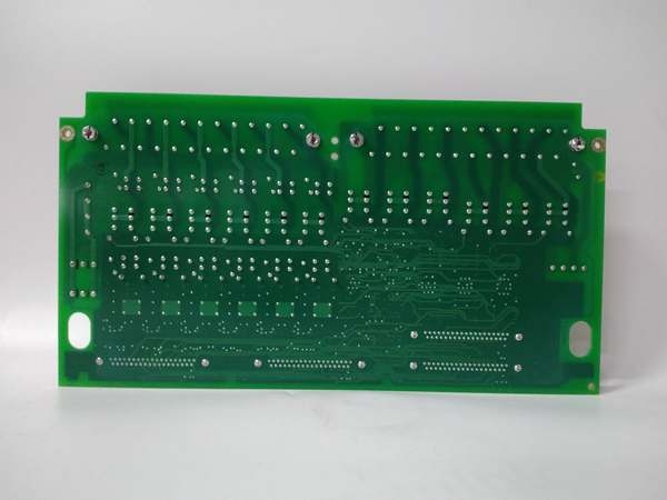
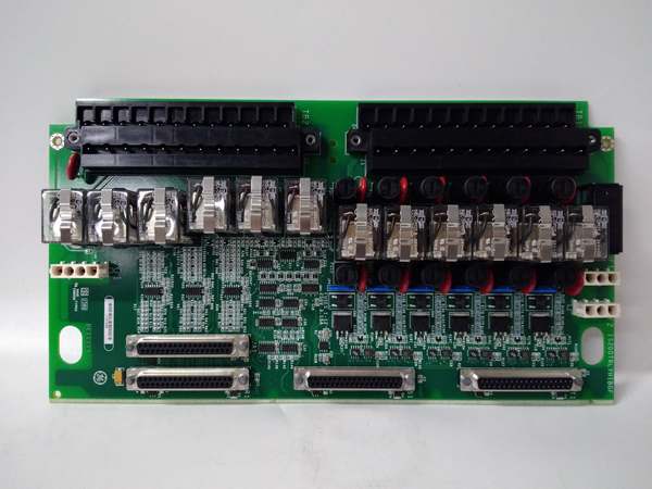
The GE is a relay terminal board serving as the high-current output stage for Mark VI turbine controls, bridging the TRLY processor to field devices like fuel trip solenoids and alarm panels. It converts low-voltage logic signals into switched 24 Vdc or 125 Vdc power for industrial actuators.
This “BGF” revision features conformal coating (G-grade) for corrosion resistance in harsh turbine environments. It houses 12 independent relays (typically SPDT), handling 2 A per contact. Actuation response is sub-10 ms once the command hits the input header, ensuring rapid turbine protection .
IS200TRLYH1BGF
Key Technical Specifications
- System Role: TRLY Terminal (Relay Outputs)
- Relay Count: 12 Independent (SPDT / Form C)
- Coil Voltage: 24 Vdc / 28 Vdc (Supplied by TRLY Processor)
- Contact Rating: 2 A @ 250 V AC / 2 A @ 30 V DC (Resistive)
- Field Voltage: 24 Vdc / 125 Vdc (Typical Trip Bus)
- Connectors: 2x 50-pin Ribbon (To TRLY Proc), Barrier Strips (Field)
- Isolation: 1500 Vrms (Coil to Contact)
- Coating: Conformal Coated (BGF – Corrosion Resistant)
- Temp Range: -40 °C to +70 °C
- Mounting: Panel Mount (Mark VI Rack/Cabinet)
Quality Control Process (Engineer’s Perspective)
- Incoming Verification: Match the GE serial to the manifest. Inspect the 12 relay bodies for cracked cases—vibration fatigue is common. Check the barrier terminal screws for galvanic corrosion on copper lugs.
- Live Functional Test: Rig with 24 Vdc coil supply and 125 Vdc load sim. Cycle all 12 relays at 1 Hz for 24 hrs. We scope the NO/NC transitions; bounce time must stay under 5 ms to avoid chattering turbine trips.
- Electrical Parameter Test: Back-probe the 24 Vdc coil input with a Fluke 115. Megger the 125 Vdc field terminals to chassis at 500 V; leakage >10 µA risks nuisance tripping during storms.
- Coating Check: Inspect the “BGF” coating near relay solder joints. Flaking coating in high-humidity plants leads to carbon tracking—well, technically it depends on the batch, but visual inspection is key.
- Final QC & Packaging: Exercise relay contacts 50 times to seat wipers. Bag in rigid ESD foam. Label “QC Passed – Relay Timing OK” with the date.
Replacement Pitfall Guide
❗ Voltage Bus Wiring: The GE usually switches the hotside of the trip bus. Landing 125 Vdc on “Common” while logic expects “NO” creates a permanent trip condition. Verify wiring diagram (Fail Safe Open vs Close).
❗ TRLY Processor Match: This is a TRLY terminal. Plugging it into a rack slot expecting TREGH (Emergency Trip) misaligns the 50-pin ribbons, potentially back-feeding 28 Vdc into a sense line and cooking the processor.
❗ Coating Compatibility: “BGF” means G-grade coating. Installing a standard (uncoated) unit in a coastal gas plant causes creepage faults on the driver traces within 6 months.
❗ Contact Rating Limits: Rated 2 A. Connecting large solenoids (e.g., 5 A inrush) welds contacts shut, failing the “Fail Safe” open requirement during shutdown.
❗ ESD to Ribbons: The 50-pin headers go to the TRLY processor. Discharge to the panel frame before unplugging—critical in dry shops (common in northern China winters).
Keep these in mind and you’ll cut 90% of rework time.
IS200TRLYH1BGF
Compatibility Matrix & Benchmarks
- GE → GE IS200TRLYH1A : Needs Adaptation — BGF is coated rev; verify jumper map for coil voltage.
- GE → GE IS200TRLY (Processor) : Direct — Physical mate for the Relay Logic Processor.
- GE → GE IS200TREGH1BEC : Incompatible — TREG is for 125V Trip Bus; TRLY is for 24V/Logic.
- Actuation Time: < 10 ms (Coil Energize to Contact Close)
- Contact Life: 100k cycles (Min, at rated load)
- Isolation Test: 1500 Vrms (Coil to Contact, 1 min)


