
Description
Product Introduction
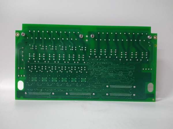
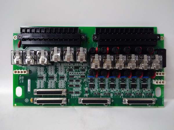
The GE is a relay terminal board serving as the high-current output stage for Mark VI turbine controls, bridging the TRLY processor to field devices like fuel trip solenoids and annunciator panels. It converts the low-voltage logic signals into switched 125 Vdc or 24 Vdc power for industrial actuators.
This “BGF” revision features a specific conformal coating for corrosive environments (G-grade) and a hardware update (B-rev). It houses 12 independent relays, typically handling 2 A per contact. Actuation response is sub-10 ms once the command hits the input header .
IS200TRLYH1BGF
Key Technical Specifications
- System Role: TRLY Terminal Board (Relay Outputs)
- Relay Count: 12 Independent (SPDT or SPST, verify with OEM datasheet)
- Coil Voltage: 24 Vdc / 28 Vdc (Supplied by TRLY Processor)
- Contact Rating: 2 A @ 125 Vdc (Resistive Load)
- Field Voltage: 125 Vdc (Typical Trip Bus), 24 Vdc (Alarm Bus)
- Connectors: 2x 50-pin Ribbon (To TRLY Proc), Barrier Strips (Field)
- Isolation: 1500 Vrms (Coil to Contact)
- Coating: Conformal Coated (BGF – Corrosion Resistant)
- Temp Range: -40 °C to +70 °C
- Mounting: Panel Mount (Mark VI Rack/Cabinet)
Quality Control Process (Engineer’s Perspective)
- Incoming Verification: Match the GE serial to the manifest. Inspect the 12 relay bodies for cracked cases—vibration fatigue is common. Check the barrier terminal screws for galvanic corrosion on the copper lugs.
- Live Functional Test: Rig with a 24 Vdc coil supply and 125 Vdc load sim. Cycle all 12 relays at 1 Hz for 24 hrs. We scope the contact closure; bounce time must stay under 5 ms to avoid chattering the turbine trip.
- Electrical Parameter Test: Back-probe the 24 Vdc coil input with a Fluke 115. Megger the 125 Vdc field terminals to chassis at 500 V; leakage >10 µA risks nuisance tripping during storms.
- Coating Check: Visually inspect the “BGF” coating near the relay solder joints. Flaking coating in high-humidity plants leads to carbon tracking and shorts—well, technically it depends on the coating batch, but inspect it anyway.
- Final QC & Packaging: Exercise relay contacts 50 times to seat the wipers. Bag in rigid ESD foam. Label “QC Passed – Relay Timing OK” with the date.
Replacement Pitfall Guide
❗ Voltage Bus Mix-up: The GE usually switches the hotside of the 125 Vdc trip bus. Landing the 125 Vdc on the “Common” terminal while the TRLY processor drives “Normally Open” creates a permanent trip condition.
❗ TRLY Processor Match: This is a TRLY terminal. Plugging it into a rack slot expecting a TREG (Emergency Trip) board misaligns the 50-pin ribbon cables, potentially back-feeding 28 Vdc into a sense line.
❗ Coating Compatibility: The “BGF” suffix means G-grade coating. Installing a standard (uncoated) unit in a coastal gas plant causes creepage faults on the relay drivers within 6 months.
❗ Contact Rating: These relays are rated 2 A. Connecting them directly to a large solenoid (e.g., 5 A inrush) welds the contacts shut, failing the “Fail Safe” open requirement.
❗ ESD to Ribbons: The 50-pin headers go to the processor. Discharge to the panel frame before unplugging—though your mileage may vary on cabinet grounding in older turbine halls.
Keep these in mind and you’ll cut 90% of rework time.
IS200TRLYH1BGF
Compatibility Matrix & Benchmarks
- GE → GE IS200TRLYH1A : Needs Adaptation — BGF is coated/HW rev; verify jumper map for coil voltage.
- GE → GE IS200TRLY (Processor) : Direct — Physical mate for the Relay Logic Processor.
- GE → Standard Relay Block : Incompatible — Handles specific VME/TRLY backplane signaling.
- Actuation Time: < 10 ms (Coil Energize to Contact Close)
- Contact Life: 100k cycles (Min, at rated load)
- Isolation Test: 1500 Vrms (Coil to Contact, 1 min)


