
Description
Hard-Numbers: Technical Specificiations
- Relay Output Channels: 12 Form-C Relays (Plug-in magnetic)
- Maximum Terminal Capacity: #12 AWG (Stranded or Solid)
- Solenoid Power Input: 125 VDC (Primary) or 115/230 VAC (Optional via jumpers)
- Coil Drive Input: 24 VDC to 48 VDC (Configurable via jumpers)
- Terminal Block Count: 2 x 24-position barrier strips
- Suppression Type: MOV (Metal Oxide Varistor) & Diode Network
- Operating Temperature: -30°C to +65°C
- Protection Features: Individual jumper-selectable fuses
- Mounting Type: DIN Rail Mounted Terminal Board
- Feedback Capability: Voting coil drive feedback (TMR ready)
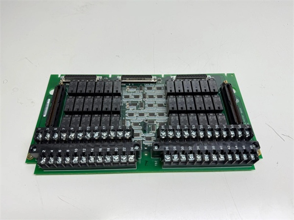
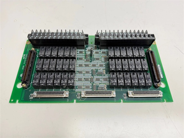
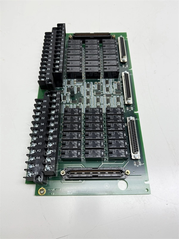
GE IS200TRLYH1BCB
The Real-World Problem It Solves
You’re troubleshooting a Mark VIe rack in a dusty, vibration-heavy gas turbine enclosure. The old terminal board’s mechanical relays are chattering under the resonant frequency of the 4160V bus duct, causing the fuel gas shut-off valve to hunt and the turbine to trip on “Valve Position Mismatch.” You need a hardened terminal board that can chew through dirty 125VDC coil power, suppress the hellacious inductive voltage spikes from the solenoids, and provide deterministic feedback to your controller. This TRLY board eliminates that nightmare. It acts as the muscle of your control system, ensuring your valves and dampers move exactly when they’re told, no matter how brutal the plant environment gets.
Where you’ll typically find it:
- Mark VIe Turbine Cabinets: Mounted on the DIN rail, driving high-current actuators, lube oil pumps, and fire suppression solenoids.
- Retrofit Projects: Replacing legacy, non-suppressed relay panels that were burning out contact tips every six months.
- Offshore & Refinery Applications: Surviving constant vibration and corrosive atmospheres where standard terminal blocks fail.
It turns a chattering, spike-prone, unreliable relay cabinet into a rock-solid, deterministic actuator driver.
Hardware Architecture & Under-the-Hood Logic
This board isn’t a processor; it’s a brutalist power interface designed to take a beating. It lives on the DIN rail next to your I/O packs, acting as the final gatekeeper between your delicate 24VDC logic and the 125VDC brute force of industrial solenoids. The “BCB” suffix indicates a specific build with enhanced trace routing and optimized jumper configurations for heavy-duty cyclic loads.
- Coil Power Acquisition & Jumper Configuration: Raw 125VDC (or 115/230VAC) lands on the heavy-duty barrier strips. Before hitting the relays, it passes through individual fuses and jumper-selected MOV/diode suppression networks. This scrubs the massive inductive kickback generated when a solenoid de-energizes.
- Plug-In Relay Activation: When the Mark VIe I/O pack sends a 24VDC or 48VDC coil drive signal, the corresponding magnetic relay slams shut. These aren’t tiny surface-mount components; they are industrial-grade plug-in relays built to handle high in-rush currents.
- Load Switching & Isolation: The relay’s Form-C contacts physically isolate the 125VDC coil circuit from the sensitive 24VDC control circuit. It delivers clean, high-amperage power directly to your field devices (valves, pumps, dampers).
- Deterministic Feedback to Controller: Integrated feedback circuits monitor the actual state of each relay coil. In TMR (Triple Modular Redundant) configurations, this feedback is used for voting logic, ensuring the controller knows exactly what the field device is doing without relying solely on dry contact status returns.
GE IS200TRLYH1BCB
Field Service Pitfalls: What Rookies Get Wrong
Using Undersized Wire for High-Inrush Solenoid Loads
A rookie lands the 125VDC power to a massive 480VAC motor-operated valve (MOV) onto the TRLY board using #16 AWG wire from a leftover spool. During a start-up, the MOV draws 15 amps of in-rush current. The undersized wire drops 3 volts, starving the MOV’s control circuit and causing it to stall halfway open. The turbine trips on “Valve Stroke Timeout.”
- Field Rule: Always check the full-load amperage (FLA) of your driven devices. Use minimum #14 AWG (2mm²) stranded copper wire for any load over 5 amps. Crimp on compression lugs rated for the wire gauge. A voltage drop on a solenoid circuit is a guaranteed recipe for a failed stroke.
Forgetting to Set the Jumper for Inductive Load Suppression
A junior engineer installs a new TRLY board to drive a bank of 24VDC fuel gas solenoids. He leaves the jumper blocks in their default positions, which lack the necessary flyback diode or MOV suppression. The first time he de-energizes the solenoids, the massive inductive voltage spike arcs across the relay contacts. He burns out six relays in a single shift.
- Quick Fix: Before landing a single wire, physically inspect and set the suppression jumpers (JP1 through JP12) according to the driven load type. DC solenoids usually require a diode; AC solenoids require an MOV. A missing suppression component will vaporize your relays in minutes.
Neglecting the Individual Fuse Holders
A mechanic notices a slight discoloration on one of the fuse holders next to Relay 3. He ignores it, thinking it’s just cosmetic aging. Six months later, a minor short in the field wiring causes the fuse to blow. The holder’s spring tension has weakened due to heat fatigue, failing to make proper contact even with a new fuse. The entire zone goes dark, and the plant suffers a costly spurious trip.
- Field Rule: During every annual outage, visually inspect and tug-test every individual fuse holder on the TRLY board. Replace any holder that shows signs of heat discoloration or loose spring tension. A bad fuse holder is a silent killer of deterministic control.
Commercial Availability & Pricing Note
Please note: The listed price is for reference only and is not binding. Final pricing and terms are subject to negotiation based on current market conditions and availability.


