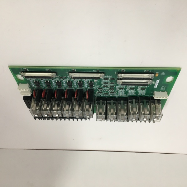
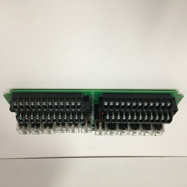
Description
System Architecture & Operational Principle
The is a passive terminal board sitting in the Mark VI cabinet, bridging the TRLY Processor (VCCC or VCRC) to the field devices. It does not execute logic itself; it receives drive commands from the processor via a 37-pin D-sub connector (JA1 for Simplex, JR1/JS1/JT1 for TMR).
Upstream, the VCCC/VCRC card decides the state (based on TMR voting logic from the controllers) and sends a low-voltage signal to energize specific relay coils on this board. Downstream, this board handles the heavy lifting: it distributes field power (typically 125V DC or 120V AC) via on-board fuses (F1-F6) to the relay commons. The output contacts (Form-C: NO/NC/Com) terminate on two removable barrier terminal blocks (24 terminals each, accepting up to #12 AWG). A critical feature is the Voted Coil Drive Feedback—the board senses actual coil current and reports back to the processor. If the coil is open or the fuse is blown, the system flags a diagnostic alarm, preventing a “silent failure” where the relay looks commanded but doesn’t physically actuate. In TMR setups, three of these boards exist (R, S, T), one per core, ensuring physical isolation of the trip paths.
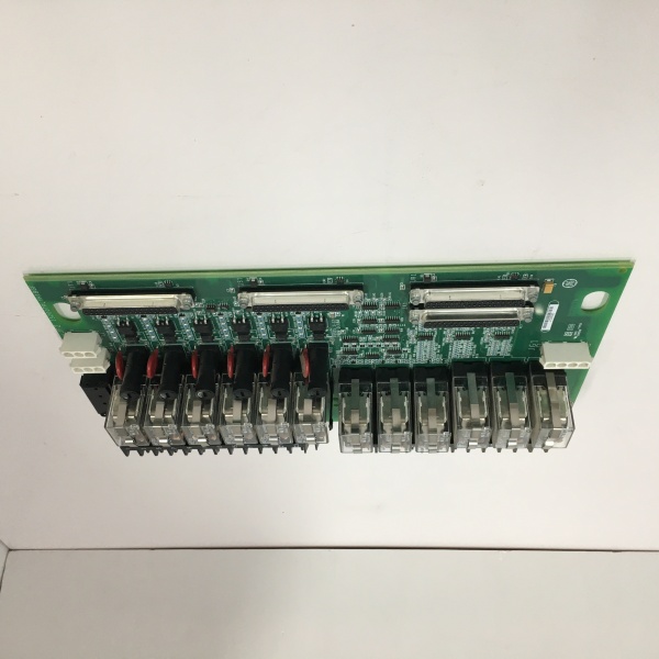
IS200TRLYH1B
Core Technical Specifications
- Relay Count: 12 Independent Form-C (SPDT) Relays
- Relay Rating (Contacts): 3A @ 125V DC (Resistive), 3A @ 120/240V AC
- Relay Rating (Coil): 24V DC (Standard Drive), Optional 125V DC config via jumpers
- Field Power Input: 125V DC or 120/230V AC (Via JF1/JF2 or TB3 terminals)
- Fusing: 6 Fused Circuits (F1-F6 for Outputs 1-6), 1 Unfused (Output 12 special), 5 Isolated Dry Contacts (Outputs 7-11)
- Terminations: 2x 24-position Barrier Strips (Accept #12 – #24 AWG)
- Processor I/F: 37-pin D-Sub (Simplex: JA1 | TMR: JR1, JS1, JT1)
- Protection: MOV Suppression on coil drives and field power inputs
- Feedback: Voted Coil Drive Sensing (Detects open coil/blown fuse)
- Mounting: Chassis Mount (Mark VI Rack) or DIN Rail (via adapter)
- Temp Range: 0°C to +60°C (Operational)
Customer Value & Operational Benefits
Positive Feedback Diagnostics
The standout value here is the Coil Drive Feedback. In a standard relay card, if a coil wire vibrates loose, the PLC says “ON” but the valve doesn’t move. The TRLYH1B measures current through the coil; if it’s zero, it tells the VCCC processor “Command Mismatch.” This gives you a “Fail-Safe Alert” before a real emergency occurs, letting you swap the board or fix the coil during a planned outage rather than discovering it during an overspeed event.
Physical Isolation & MTTR
The relays are socketed (plug-in), not soldered. If Output 3 sticks due to a dirty contact from a nearby contactor arc, you don’t replace the $2k board. You pull the 5-cent relay, pop in a new one. This cuts MTTR (Mean Time To Repair) from hours (rerouting wires to a new card) to minutes. The barrier terminals are also removable, so you can unplug the field wires, swap the board, and plug the block back in without re-terminating 48 wires.
TMR Channel Separation
In a TMR config, this board ensures R, S, T channel isolation. Output 1-R, 1-S, and 1-T are on separate physical boards. A short circuit on the R-core’s solenoid (e.g., a wire rubbed through on a vibration damper) will blow the fuse on the R-board but leave S and T operational, maintaining the 2oo3 vote and keeping the unit online.
Field Engineer’s Notes (From the Trenches)
The “Gotcha” on the H1B is the Fusing vs. Application on the first six relays. Outputs 1-6 are fused (F1-F6), but you have to install those fuses. I’ve seen techs install the board, wire up the Fuel Trip Solenoid to Output 1, and wonder why nothing happens. The fuse clip was empty from the factory (shipped in the bag).
Also, watch the Jumper Settings for Coil Voltage. The board supports 24V DC (default) and 125V DC coil drives via JP1-JP6. If your VCCC is sending 24V signals but you left the jumpers on “125V,” the relays will chatter or not pull in at all because of the voltage divider network on the board.
Lastly, Torque those barrier terminals. These handle 125V DC trip power. A loose “Common” wire on Output 1 creates an intermittent connection; the turbine runs fine until it hits a resonant frequency, the wire arcs, and you get a spurious “Trip A” signal. Use a 0.5 Nm driver, not just “hand tight.”
Real-World Applications
- Gas Turbine Fuel Stop Valve (FSV) Control: Output 1 (R, S, T) drives the three redundant solenoids on the FSV. The TRLYH1B provides the 125V DC contact closure. If R’s fuse blows, S and T still hold the vote, and the “Coil Feedback” alarm tells you to swap it during the next cooldown.
- Lube Oil Pump Interlocks: Outputs 7-11 (Isolated Dry Contacts) are often used here. They don’t switch field power on the board; they just provide a dry contact to the Motor Control Center (MCC). This keeps the 125V DC turbine bus isolated from the 480V AC pump starters.
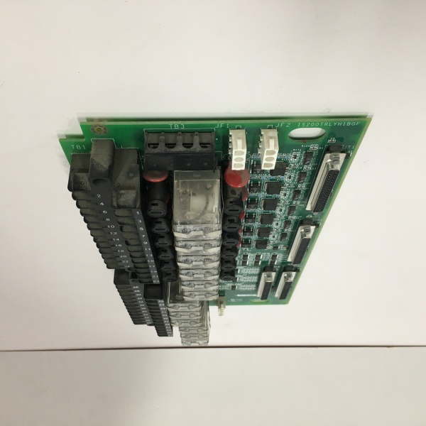
IS200TRLYH1B
High-Frequency Troubleshooting FAQ
Q: ToolboxST shows “TRLY Diagnostic Alarm – Coil Drive Fail” on Channel 1. The relay clicks when I manually test it. What’s wrong?
A: The relay clicking means the coil has continuity, but the Feedback circuit (sensing resistor network on the board) is likely detecting a voltage drop issue. Check Fuse F1. Even if it’s not blown, the holder might have corrosion (high resistance). Clean the fuse clips with contact cleaner. If the fuse is good, the VCCC processor’s feedback input might be skewed, or the ribbon cable (JA1/JR1) has a pin with high resistance—wiggle the D-sub connector while watching the diag.
A: Yes, but you must rewire the power distribution. Land your 24V DC supply on JF1/JF2 (instead of 125V). Crucially, remove Jumper JP1-JP6 if you are using 24V coils and24V field power on the same terminal, otherwise the internal voltage divider will starve the relay coil. For pure dry contacts (Outputs 7-11), voltage doesn’t matter as long as you stay under the 3A/250V rating.
Q: Replacing a failed board in a TMR system—do I need to power down the whole rack?
A: Ideally, yes, for a terminal board with field power landed on it, LOTO the 125V/24V field supply at the PDM. While the TRLY logic connects via the D-sub (which is “live” from the VCCC), swapping the board with field power active risks a screwdriver slip bridging the 125V Common to the chassis, which will trip your whole rack’s 125V bus. Don’t risk it for a 5-minute power down.
Please note: The listed price is not the actual final price. It is for reference only and is subject to appropriate negotiation based on current market conditions, quantity, and availability.