
Description
Hard-Numbers: Technical Specifications
- Sync Link Voltage: 24 VDC (Nominal, range 20-28VDC)
- Sync Link Current Draw: < 500 mA per controller link
- Isolation Rating: 1500V AC (Sync bus to backplane logic)
- Operating Temperature: -40°C to +85°C
- Redundant Architecture Support: 2oo3 (Two-out-of-Three) Voting Logic
- Communication Interface: Proprietary Sync Link (Hardwired)
- Trip Relay Outputs: Redundant Form-C Relays (250VAC/30VDC rating)
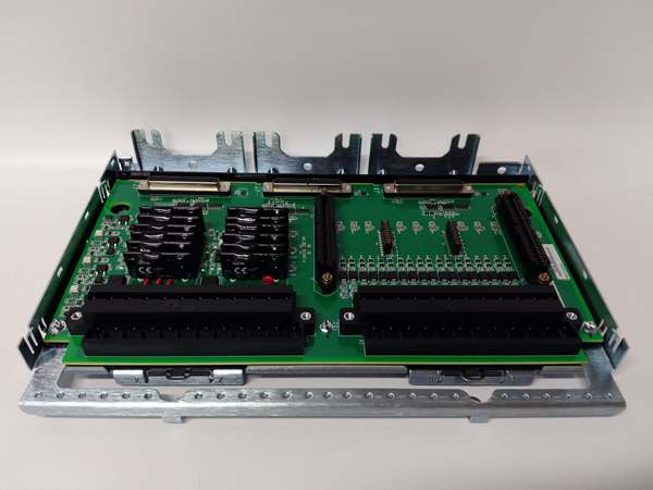
- Mounting Location: Exciter Power Backplane Rack (EPBP)
- Diagnostic LEDs: Sync Active (M1/M2/C), Fault, Relay Energized
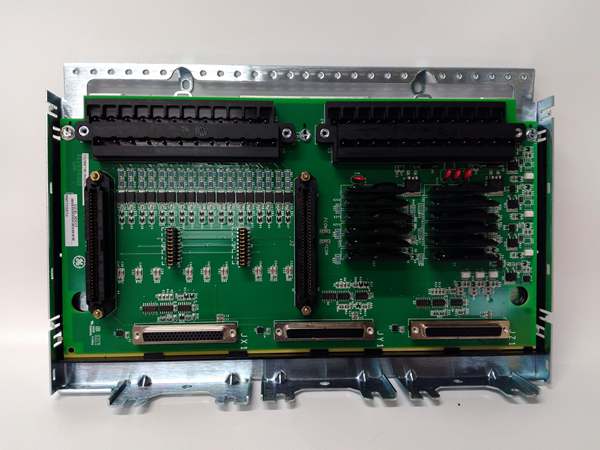
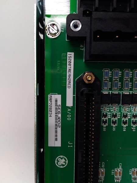
GE IS200TREAH2ACC
The Real-World Problem It Solves
You’re troubleshooting a 9FA gas turbine that just suffered a catastrophic “Loss of Excitation” trip during a planned maintenance outage. The root cause? The old redundant interface card didn’t detect a dying M1 controller until it was too late, forcing a millisecond-long gap in gate pulse generation during the handoff to M2. You need a board that can arbitrate between three controllers in the blink of an eye, using hardwired 24VDC sync links to guarantee zero-loss handovers.
Where you’ll typically find it:
- EX2100e / Mark VIe Exciter Cabinets: Mounted on the EPBP backplane, facilitating the 2oo3 voting logic for M1, M2, and C controllers.
- Nuclear and Large Combined-Cycle Plants: Where a single second of excitation loss can trigger a reactor scram or a $500,000 steam turbine overspeed.
- Retrofit Projects: Upgrading legacy simplex or dual-redundant static exciters to full triple-modular redundancy (TMR).
It turns a terrifying millisecond control gap into a guaranteed, deterministic, and seamless transition between redundant controllers.
Hardware Architecture & Under-the-Hood Logic
This board isn’t a standalone processor; it’s a deterministic voting engine and synchronization arbiter built for the harshest electrical environments. It lives on the EPBP backplane, acting as the supreme judge of who is in charge of your multi-million dollar generator. The “ACC” suffix indicates project-specific firmware and optimized trace routing for mission-critical, zero-downtime applications.
- Sync Link Acquisition & Health Monitoring: Three hardwired 24VDC sync links arrive from the M1, M2, and C controllers. Dedicated comparators on the TREA constantly monitor the voltage and pulse integrity of these links to detect a failing controller before it drags down the system.
- 2oo3 Voting Logic Execution: When a “Master Request” comes in from multiple controllers, the onboard logic executes a hardware-level 2oo3 (Two-out-of-Three) vote. It instantly identifies the majority consensus to prevent split-brain scenarios that could destroy the thyristor bridge.
- Deterministic Handoff Triggering: Upon detecting a Master controller failure, the TREA doesn’t wait for software polling. It instantly gates the sync bus to the healthiest backup controller, ensuring the gate pulses never drop below the thyristor holding current.
- Redundant Trip Relay Latching: If a catastrophic failure is detected, the TREA drives its redundant Form-C relays. These provide a hardwired, fail-safe path to the turbine protection system, ensuring the generator breaker opens even if the DCS goes dark.
GE IS200TREAH2ACC
Field Service Pitfalls: What Rookies Get Wrong
Using Standard 63/37 Leaded Solder on RoHS 6/6 (Lead-Free) Hardware
A rookie tech spots a cold solder joint on the sync link terminal block of a “ACC” board and whips out his trusty 350°C leaded soldering iron. The lead-free solder on the board has a much higher melting point. He cranks the iron to 430°C, delaminates the copper trace, and destroys the board’s internal isolation barrier. A week later, a massive inductive voltage spike jumps the gap, frying the entire EPBP rack.
- Field Rule: Never attempt to solder or rework RoHS 6/6 hardware in the field. These boards require specialized lead-free solder paste and precise temperature-controlled reflow ovens. If you spot a physical defect, RMA the board to a certified repair center.
Cross-Wiring the 24VDC Sync Links Between Controllers
A junior engineer is landing the sync links from controllers M1 and M2 onto the TREA. In a moment of distraction, he swaps the positive and negative leads for the M2 link. The TREA detects a reverse-polarity voltage on the sync bus. It immediately triggers a “Sync Link Conflict” alarm, locks out the M2 controller, and forces the system into simplex mode, negating your entire redundant architecture.
- Quick Fix: Before tightening a single screw, use a multimeter to verify the polarity of every 24VDC sync link at the wire ends. Match the color codes exactly to the legacy drawings. A reversed polarity on a sync link is a silent killer of triple-redundant systems.
Routing Sync Links Parallel to High-Voltage Thyristor Bus Work
A mechanic is dressing the 24VDC sync link cables in the EPBP rack. To save space, he zip-ties them directly to the 4160V thyristor bus duct for 10 feet. The sheer electromagnetic field radiating from the bus duct induces massive common-mode noise into the sync links. The TREA misinterprets the noise as a “Controller Heartbeat Loss,” initiating a spurious handoff that trips the entire excitation system.
- Field Rule: Route 24VDC sync links using shielded twisted pair (STP). Maintain a minimum separation of 12 inches from any high-voltage bus work or transformer tanks. Ground the shield drain wire at the TREA terminal end only to prevent ground loops.
Commercial Availability & Pricing Note
Please note: The listed price is for reference only and is not binding. Final pricing and terms are subject to negotiation based on current market conditions and availability.


