
Description
Product Introduction
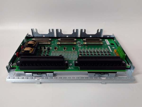
The GE is a protection terminal board serving as the field interface for Mark VIe turbine controls, bridging sensors like magnetic pickups and pressure transmitters to the VPRO processor. It handles the raw signals that determine if the turbine requires an emergency shutdown due to overspeed or high bearing temperature.
This “CBB” revision includes conformal coating for corrosion resistance in harsh turbine bays. It supports 8 analog inputs (4-20 mA or TC/RTD via config) and 6 discrete inputs for alarm contacts. Signal conditioning happens on-board before hitting the backplane, with response times typically under 10 ms for trip initiation .
GE IS200TPROS1CBB
Key Technical Specifications
- System Role: TPROS Terminal (Protection I/O)
- Analog Inputs: 8 Channels (4-20 mA, 0-10 V, or TC/RTD via jumpers)
- Discrete Inputs: 6 Channels (Dry Contact, 24 Vdc Wetting)
- Logic Voltage: 24 Vdc / 28 Vdc (From VPRO Processor)
- Input Isolation: 1500 V DC (Channel-to-Ground/Backplane)
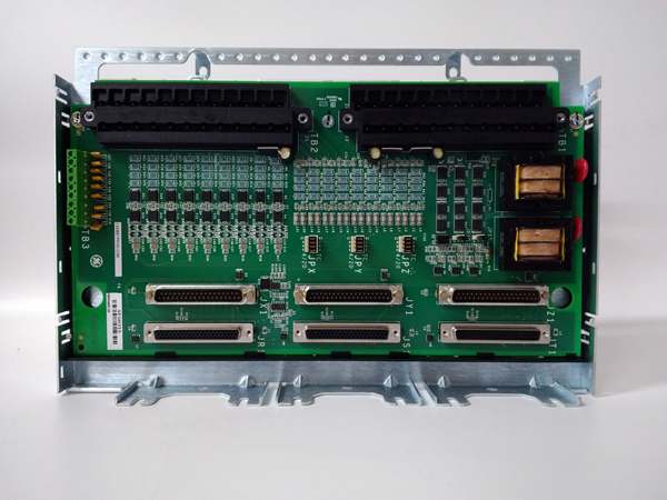
- Connectors: Pluggable Euro-Terminals (Field), 50-pin D-Sub (To VPRO)
- Coating: Conformal Coated (CBB Revision)
- Temp Range: -30 °C to +65 °C (Operational)
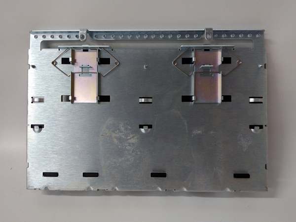
- Mounting: Mark VIe Backplane Slot / Panel Mount
- Trip Integration: Votes with TPRO cards in TMR setups
Quality Control Process (Engineer’s Perspective)
- Incoming Verification: Match the serial on the GE to the manifest. Inspect the pluggable terminal blocks for cracked levers—common after removal. Check the conformal coating near the high-voltage traces for carbon tracking.
- Live Functional Test: Rig with a VPRO simulator. Inject 4-20 mA simulating high bearing temp. We scope the output to the processor; signal lag must stay under 5 ms to meet protection timing.
- Electrical Parameter Test: Back-probe the 24 Vdc logic feed with a Fluke 115. Megger the analog input terminals to chassis at 500 V; leakage must hold >10 MΩ to survive switchyard transients.
- Jumper Verification: Photograph the input type jumpers (AI range select). Forgetting a “4-20mA” vs “TC” strap inverts the scaling—well, technically software fixes it, but hardware limits the input impedance.
- Final QC & Packaging: Torque test a terminal screw (0.5 Nm). Bag in rigid ESD foam. Label “QC Passed – Protection Loop OK” with the date.
Replacement Pitfall Guide
❗ TMR Context: The GE is often one leg of a TMR protection triplet. Mixing this “CBB” revision with older “B” or “A” revisions in the same rack causes “Hardware Mismatch” votes and inhibits the trip logic.
❗ Input Strapping: Terminals support 4-20 mA, TC, and RTD. Landing a 4-20 mA transmitter on a terminal jumpered for “Thermocouple” results in unreadable noise and “Sensor Fail” alarms.
❗ Wetting Voltage: The 6 DI channels often use 24 Vdc from the VPRO. If the processor rack is powered down (or PSU sag), the inputs float, triggering spurious “Trip Block” alarms.
❗ Shield Grounding: Sensor shields (especially for Speed Pickups) terminate at the single-point ground lug on the terminal block. Grounding at the probe andthe board creates a ground loop, injecting 60 Hz hum that masks overspeed signals.
❗ ESD to Header: The 50-pin D-Sub goes to VPRO. Discharge to the panel frame before unplugging—critical in dry turbine halls (common in northern China winters).
Keep these in mind and you’ll cut 90% of rework time.
GE IS200TPROS1CBB
Compatibility Matrix & Benchmarks
- GE → GE IS200TPROS1CB : Direct — CBB is coated rev; verify jumper map matches site config.
- GE → GE IS200VPRO (Processor) : Direct — Physical mate for the Protection Processor.
- GE → Standard Terminal Block : Incompatible — Handles specific VPRO backplane signaling and trip voting.
- Trip Response: < 10 ms (Signal valid to Logic Out)
- Input Accuracy: ±0.1% Full Scale (Typical, verify with OEM datasheet)
- Isolation Test: 1500 V DC (Channel to Logic Bus)


