
Description
System Architecture & Operational Principle
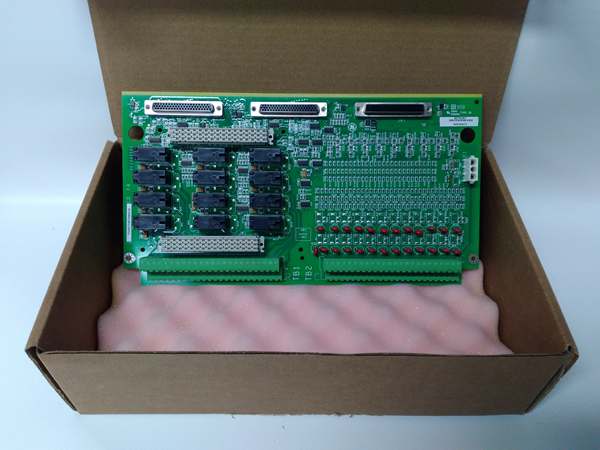
The is a passive terminal board residing at Level 1 (Field Termination) in a Mark VIe TMR (Triple Modular Redundant) architecture. It does not execute logic; it serves as the physical nexus where your field wires meet the control system.
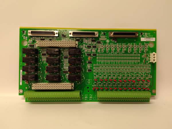
Physically, it mounts on a DIN rail (via a metal carrier) inside the turbine cabinet. It interfaces with three IS220PDIOH1A (or H1B) I/O packs simultaneously via three 37-pin D-sub connectors (JR1 for R, JS1 for S, JT1 for T). Upstream, the PDIO packs process the signals and talk to the controller over IONet. Downstream, this board handles the heavy lifting: it accepts 125 V DC field power (landed on TB1/TB2) to “wet” the dry contacts (switches, limit switches) and drive the coils of external interposing relays or solenoids.
The “6A” in the suffix is the smoking gun: it denotes 125 V DC compatibility. This board includes specific voltage dividers and suppression components (MOVs) rated for higher voltages compared to the “H2A” (24V) variant. In a TMR setup, you will have three PDIO packs plugged into one TDBTH6A, ensuring that a wiring fault on the ‘R’ field device doesn’t drag down the ‘S’ and ‘T’ logic paths, preserving the 2oo3 vote.
IS200TDBTH6A
Core Technical Specifications
- Input Channels: 24 (Group-Isolated Dry Contact Sensing)
- Output Channels: 12 (Form-C Relay Driver Outputs – switches ground to coil, not power)
- Wetting/Field Voltage: 125 V DC (Nominal Range 100-145V DC)
- Input Current Limit: 2.5 mA (Ch 1-21), 10 mA (Ch 22-24)
- Output Drive Cap: Low-Side Switch (Sinks ~1A to drive external relay coils)
- I/O Pack Interface: 3x 37-pin D-Sub (JR1, JS1, JT1 for R, S, T)
- Field Terminals: 2x 48-Position Barrier Strips (TB1 for Relays, TB2 for Inputs)
- Protection: MOVs (Surge Suppression) on inputs, PTC Resettable Fuses
- Isolation: Group Isolation on Inputs, Channel-to-Channel (via PDIO Optos)
- Mounting: 35mm DIN Rail (TS-35) with Metal Carrier/Bracket
- Environmental: -30°C to +65°C, Conformal Coated (H6A Rev)
Customer Value & Operational Benefits
TMR Field Isolation
The primary value here is physical separation of redundant field circuits. Since one TDBTH6A board hosts the wiring for R, S, and T PDIO packs, GE designed the PCB traces to be highly isolated. If a 125V DC field wire chafes against the panel and shorts to ground on the “R” input block, the “S” and “T” channels on the same physical board usually survive due to the creepage distance and trace routing. This preserves your 2oo3 vote and keeps the unit online during a vibration-induced wiring failure.
Voltage Standard Alignment
The “H6A” is built for 125V DC turbine standards. Trying to use a 24V board (H2A) in a 125V plant will cook the input resistors; using this H6A in a 24V system results in “dead” inputs (voltage too low to cross the threshold). Having the correct H6A on hand means you don’t have to re-wire the field supply or add interposing relays just to match the I/O pack’s expectations.
Diagnostic Clarity
Because the wiring is centralized on this board’s barrier terminals, you can stick a multimeter on TB2-3 while the turbine is running (carefully) to verify if that “Lube Oil Pump Run” contact is actually closing at the field device, versus guessing if the PDIO pack is reading it right. It cuts troubleshooting time from 30 minutes to 2 minutes.
Field Engineer’s Notes (From the Trenches)
The “Gotcha” on the TDBTH6A is the Output Wiring Logic. This board provides Relay Drivers, not power-switching relays. The terminals on TB1 (Outputs) are the Low-Side Switch (Sinking).
You must land your 125V DC Positive (+) supply on the coil of the external relay/solenoid, and land the Negative (-/Return) from the coil onto the TDBTH6A terminal. When the PDIO commands ON, the TDBT closes the path to ground. If you wire 125V+ directly to the TDBT terminal thinking it’s a dry contact or source, you will instantly blow the PTC fuse (F1-F6) or fry the driver transistor on the PDIO pack.
Also, Torque those D-Sub screws (JR1/JS1/JT1). Turbine decks vibrate. I’ve seen the 37-pin connector loosen by 1/4 turn over six months, causing intermittent “I/O Pack Not Responding” errors that look like a 0.02 screw. Use a dab of vibratite or nylon lock nuts on the D-sub thumbscrews if the vibration is chronic.
Real-World Applications
- Steam Turbine EHC System (TMR): Three PDIO packs (R, S, T) plug into one TDBTH6A. Inputs 1-3 read “Trip Solenoid A De-energized” (125V DC wetting) from the three redundant trip legs. Outputs 1-3 drive the coil of the SRLY (Slave Relay) which actually breaks the power to the main trip solenoids. The 125V rating handles the noisy EHC pump VFD environment.
- Combined Cycle Startup Sequencer: Monitoring “GT Synchro Check” and “Steam Admission Valve Limit” switches. The H6A handles the 125V DC signals from the older relay-logic panels interfacing with the new Mark VIe system without needing signal converters.
IS200TDBTH6A
High-Frequency Troubleshooting FAQ
A: Check your Common (Return) Wiring. The inputs are “Wetted” (sourced). You need 125V DC Positive on the input terminal (TB2) AND the Negative (DC Return) landed on the specific “Common” terminal for that input group. If the common is loose or landed on a different voltage potential (like 24V RTN), the sensing current won’t flow, even though the hot leg reads 125V. Also, verify the PTC Fuse (little black blob near the connector) hasn’t tripped from a previous short; measure resistance across the input—if open, wait for it to cool/reset.
A: No. The hardware thresholds are different. The H2A expects ~24V to cross the “ON” threshold; the H6A expects ~100V+. If you put an H6A in a 24V system, the inputs will likely stay “OFF” (0) because 24V < 100V. Electrically, the connectors fit, but the system won’t function. You must match the board revision (H2A for 24V sites, H6A for 125V sites) to the field voltage standard.
A: The PDIO pack reads an ID chip on the terminal board. If you swapped a TDBS (Simplex) for a TDBT (TMR) or changed revisions, the controller’s I/O configuration (.acffile) won’t match. Open ToolboxST -> I/O Configuration, right-click the PDIO pack, select “Detect Terminal Board,” and download the configuration. If the physical wiring is TMR (3 packs on one board), ensure the software config is set to “TDBT”, not “TDBS”.
Please note: The listed price is not the actual final price. It is for reference only and is subject to appropriate negotiation based on current market conditions, quantity, and availability.


