
Description
System Architecture & Operational Principle
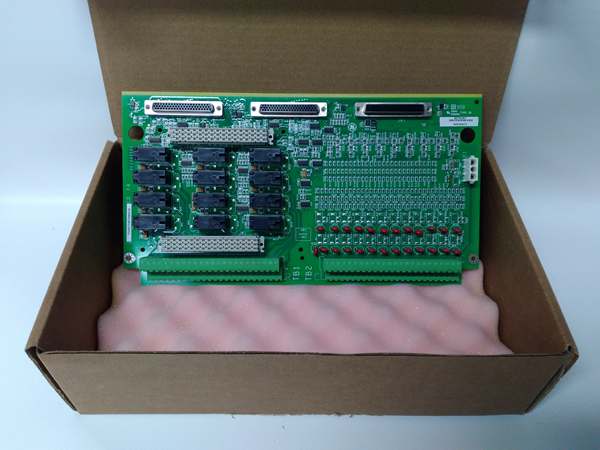
The is a passive terminal board operating at Level 1 (Field Interface) of the Mark VIe architecture. It is the Simplex counterpart to the TDBTH (TMR) board. Its sole job is to terminate field wires and interface with one IS220PDIOH1A (or H1B) I/O pack via a 37-pin DC-62 connector (JH1).
Upstream, the PDIO pack processes signals and talks to the controller over IONet (Ethernet). Downstream, this board handles the heavy lifting for field devices. The “6A” suffix is critical: it denotes 125 V DC compatibility. This board includes specific voltage dividers and Metal Oxide Varistors (MOVs) sized for 125V transients, unlike the H2A (24V) version. It accepts an external 125V DC supply (landed on TB2) to “wet” the 24 dry-contact inputs (providing the sensing current). For outputs, it acts as a low-side switch (sink), controlling the ground path to drive external interposing relay coils (e.g., SRLY) or solenoids. There is no voting logic on this board; it’s a straight 1:1 pass-through for non-redundant auxiliary systems (lube skids, balance-of-plant).
IS200TDBTH6A
Core Technical Specifications
- Architecture: Simplex (Single PDIO Pack Interface)
- Input Channels: 24 (Group Isolated Dry Contacts)
- Input Voltage (Wetting): 125 V DC (Nominal Range 100-145V DC)
- Input Threshold: ~50% of Wetting Voltage (e.g., ~62.5V for 125V)
- Input Current Limit: 2.5 mA (Ch 1-21), 10 mA (Ch 22-24)
- Output Channels: 12 (Form-C Relay Drivers / Low-Side Switches)
- Output Capability: Sinks ~1A @ 28V DC (to drive external relay coils)
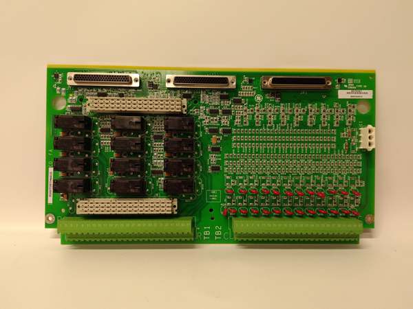
- I/O Pack Interface: 1x 37-pin D-Sub (JH1 to IS220PDIOH1A)
- Field Terminals: TB1 (Relay Outputs), TB2 (Input Commons/Power)
- Protection: MOVs on inputs (125V rated), PTC Resettable Fuses
- Isolation: Group Isolation on Inputs (Shared Commons per group)
- Mounting: 35mm DIN Rail (TS-35) with Metal Carrier
- Environmental: -30°C to +65°C, Conformal Coated (H6A Rev)
Customer Value & Operational Benefits
Voltage Standard Alignment
The “H6A” is built for 125V DC turbine/utility standards. In plants where the auxiliary bus is 125V DC, using a 24V board (H2A) requires adding interposing relays to step up the voltage. The H6A handles 125V natively on the input sensing side, reducing panel clutter and eliminating points of failure introduced by extra relay interfaces.
Simplex MTTR Reduction
For non-critical loops (e.g., “Cooling Fan Running” status), you don’t need TMR complexity. This board lets you deploy a single PDIO pack with a robust termination interface. If a field wire shorts, the PTC fuse on the TDBS pops locally; you clear the fault, reset the PTC (or swap the $500 board), and you’re back online in 10 minutes without disturbing redundant cores.
Wiring Durability
The barrier terminals (TB1/TB2) accept up to #12 AWG, which is standard for 125V DC field runs (thicker insulation/jacket). The board layout separates Inputs (Lower TB2) from Outputs (Upper TB1), preventing a mis-placed 125V lead from jumping into a low-voltage sensor circuit.
Field Engineer’s Notes (From the Trenches)
The “Gotcha” on the H6A is the Output Wiring Logic. This board provides Relay Drivers (Low-Side Switches), not power-switching relays.
You must land your 125V DC Positive (+) on the coil of the external relay/solenoid, and land the Negative (-/Return) from the coil onto the TDBSH6A terminal (TB1). When the PDIO commands ON, the TDBS closes the path to Ground (DGND).
If you land 125V+ directly to the TDBS terminal thinking it’s a dry contact, you will instantly blow the PTC fuse (F1-F6) or fry the driver transistor on the PDIO pack ($3k mistake).
Also, Torque those 125V terminals. Unlike 24V systems where a loose wire just causes a “0” reading, a loose 125V+ wire on TB2 can arc to the DIN rail (ground) during a vibration event, tripping your whole plant’s 125V DC bus. Use a torque screwdriver (0.5-0.6 Nm), not just a “tight” feeling.
IS200TDBTH6A
Real-World Applications
- Auxiliary Lube Oil Skid (Simplex): One PDIO pack plugs into the TDBSH6A. Inputs 1-10 read “Pump Run” (125V wetting) and “Strainer Clog” from the skid. Outputs 1-2 drive the 125V DC coils of the SRLY (Starter Relay) for the lube oil pumps. No TMR needed here; a pump failure is handled by auto-changeover logic, not a turbine trip.
- Balance of Plant (BOP) Interlocks: Monitoring “Cooling Water Flow” switches for a generator air cooler. The 125V DC signals from the old plant relay panels interface directly to the TDBSH6A without signal converters, simplifying integration with legacy systems.
High-Frequency Troubleshooting FAQ
Q: My PDIO pack reads “0” on Input 1, but I measure 125V DC at the TDBSH6A terminal (TB2-3). Is the board bad?
A: Check your Common (Return) Wiring. The TDBSH6A inputs are “Wetted” (sourced). You need 125V DC Positive on the input terminal (TB2) AND the Negative (DC Return) landed on the specific “Common” terminal for that input group. If the common is loose or landed on a 28V RTN (mixed voltages), the sensing current won’t flow, even though the hot leg reads 125V. Also, verify the PTC Fuse (little black blob) hasn’t tripped from a previous short; measure resistance across the input—if open/high ohms, let it cool/reset.
A: Electrically, No. The hardware thresholds are different. The H2A expects ~24V to cross the “ON” threshold; the H6A expects ~100V+. If you put an H6A in a 24V system, inputs will likely stay “OFF” (24V < 100V threshold). If you put an H2A in a 125V system, you risk exceeding the input resistors’ voltage rating, potentially causing thermal damage to the board or sending over-voltage spikes back to the PDIO pack’s opto-isolators. Match the revision to the field voltage standard.
Q: The PDIO pack faults with “Hardware Mismatch” after I installed the TDBSH6A.
A: The PDIO pack reads an ID chip on the terminal board. If your controller project (ToolboxST) is configured for TDBT (TMR) or TDBSH2A (24V), it will fault. Open ToolboxST -> I/O Configuration, right-click the PDIO pack, select “Detect Terminal Board,” and download the configuration to align the software with the physical hardware.
Please note: The listed price is not the actual final price. It is for reference only and is subject to appropriate negotiation based on current market conditions, quantity, and availability.


