
Description
Product Introduction
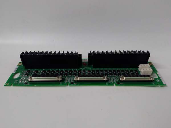
The GE is a terminal interface board designed for the Mark VIe TMR (Triple Modular Redundant) architecture, bridging field wiring to the TBCI I/O processor pack. It handles 16 configurable channels, settable as inputs (dry contact sensing) or outputs (0.5 A drive), keeping the high-voltage field side away from the sensitive backplane.
This “D” revision () improves on earlier versions with better short-circuit protection on outputs and enhanced noise filtering on inputs. In a TMR triplet, three of these boards vote on signal states; a mismatch triggers diagnostics in ToolboxST within 10 ms. The unit mounts via DIN rail or panel screws, passing 24 Vdc logic from the processor via a 50-pin ribbon .
GE IS200TBCIS2CCD
Key Technical Specifications
- System Role: TBCIS Terminal (TMR Discrete I/O)
- Channels: 16 Configurable (Input or Output per channel)
- Logic Voltage: 24 Vdc (Range 18–32 Vdc)
- Output Rating: 0.5 A per channel (Max 4 A total board)
- Input Type: Dry Contact (Requires 24 Vdc excitation from TBCI)
- Isolation: 500 V AC (Channel-to-Ground/Backplane)
- Response Time: < 10 ms (Input Scan), < 15 ms (Output Update)
- Diagnostics: Open Wire Detect (Inputs), Short Circuit Protect (Outputs)
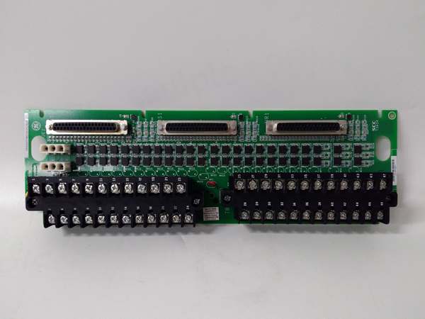
- Connectors: Pluggable Euro-Terminal Blocks (Field), 50-pin D-Sub (Proc)
- Temp Range: -30 °C to +65 °C (Operational)
- Compliance: SIL-2 Capable (In TMR Architecture), CE/UL
Quality Control Process (Engineer’s Perspective)
- Incoming Verification: Match the GE serial to the manifest. Inspect the pluggable terminal blocks for cracked plastic levers—common after removal. Check the 50-pin header for bent pins; forced insertion kills the TBCI pack.
- Live Functional Test: Rig with a TBCI simulator. Configure 8 ch as Input, 8 as Output. Cycle outputs at 1 Hz; we scope the rise time—must be clean without ringing to pass the 0.5 A load test.
- Electrical Parameter Test: Back-probe the 24 Vdc feed with a Fluke 115. Megger the field terminals to chassis at 500 V; leakage must hold >10 MΩ to survive switchyard transients.
- Config Verification: Photograph the channel usage sticker (if present). Forgetting a “Input/Output” strapping jumper (if HW config needed) feeds 24 Vdc back into a sense line—well, technically most is soft-config in .cfg files, but verify rev specifics.
- Final QC & Packaging: Torque test a terminal screw to check clamp tension (0.5 Nm). Bag in rigid ESD foam. Label “QC Passed – I/O Loop Verified” with the date.
Replacement Pitfall Guide
❗ TMR Voting Logic: The GE is part of a triplet (A, B, C). Replacing just one unit with a different hardware revision (e.g., Rev C) causes “Hardware Mismatch” alarms and inhibits voting.
❗ Channel Direction: Unlike fixed I/O, these 16 channels are configurable. Swapping a board without loading the matching .cfgfile reverses Input/Output states—connecting a dry contact to an output channel fries the driver instantly.
❗ Power Feed Polarity: The 24 Vdc logic feed (usually P1/P2) is polarized. Reversing the wires on the terminal block back-feeds negative voltage into the TBCI processor, tripping the rack’s protection.
❗ Shield Grounding: The cable shield drain wire lands on the specific ground lug (often the mounting screw). Grounding at the field device andthe terminal board creates a ground loop, injecting noise that fools the 10 ms scan.
❗ ESD to Ribbon: The 50-pin header goes to the TBCI processor. Discharge to the panel frame before unplugging—critical in dry turbine halls (common in northern China winters).
Keep these in mind and you’ll cut 90% of rework time.
GE IS200TBCIS2CCD
Compatibility Matrix & Benchmarks
- GE → GE IS200TBCIS2CCB : Needs Adaptation — Rev D adds protection; verify .cfg file supports the hardware change.
- GE → GE IS200TBCI (Processor) : Direct — Physical mate for the TMR Discrete I/O Pack.
- GE → Standard Terminal Block : Incompatible — Handles specific TMR voting signals and 50-pin ribbon mapping.
- Scan Time: < 10 ms (Input Debounce/Read)
- Vote Resolution: < 20 ms (TMR Mismatch Detection)
- Isolation Test: 500 V AC (Field to Logic Bus, 1 min)


