
Description
System Architecture & Operational Principle
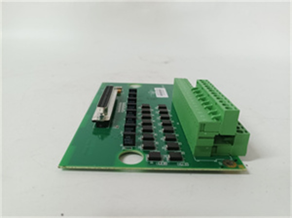
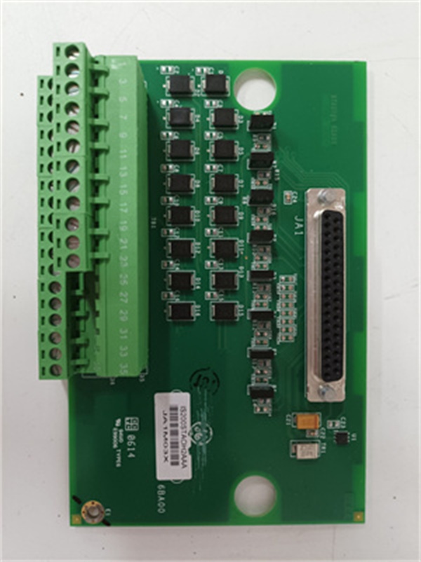
The is a DIN-rail mounted terminal board, not a processor. It resides in the turbine control cabinet, bridging the gap between field thermocouples (bearing temp, exhaust temp, flame scanners) and the Mark VIe I/O pack (typically a PAICH1A Analog Input pack).
Physically, field wires terminate on its removable screw terminals. The board houses the Cold Junction Compensation (CJC) sensor and signal conditioning electronics (filtering, MOV surge suppression). It connects to the I/O pack via a short ribbon cable (50-pin IDC). Upstream, the I/O pack digitizes the millivolt signals and passes them over IONet (Ethernet) to the controller (UCVE). Downstream, this board outputs conditioned voltage drops representing temperature to the ADCs on the pack. In TMR (Triple Modular Redundant) setups, you will have three of these boards (R, S, T), one feeding each I/O pack, ensuring that a wiring fault on one channel doesn’t kill the turbine trip logic. It operates purely at the signal interface layer—Level 1 of the Purdue Model—handling the messy real-world voltages so the digital backbone doesn’t have to.
IS200STCCH2A
Core Technical Specifications
- Channel Density: 16 Isolated Thermocouple Inputs
- Supported Types: J, K, T, E, R, S, B (Software Selectable per channel)
- Signal Range: -10 mV to +100 mV (Typical TC spans)
- CJC Accuracy: ±0.5°C (Built-in sensor on PCB)
- Isolation: Channel-to-Channel / Channel-to-Earth (Via Opto/Transformers on Pack)
- Termination: Removable Screw Terminals (Accepts 12-24 AWG)
- Interface to I/O Pack: 50-pin IDC Ribbon Cable (To PAICH1A/PAICA)
- Power: Derived from I/O Pack (24V DC passed via ribbon)
- Environmental: -20°C to +60°C (Operational), Conformal Coated (H2A Rev)
- Protection: Onboard MOVs (Metal Oxide Varistors) for surge suppression
- Mounting: Standard 35mm DIN Rail (TS-35)
Customer Value & Operational Benefits
Signal Integrity in High-EMI Zones
Turbine decks are electrically noisy (VFDs, arc flashes, thyristor switching). The STCC board isn’t just a terminal block; it has hardware filtering (50/60Hz notch filters) and surge protection baked in. This keeps your exhaust temp readings stable during load swings, preventing nuisance trips from electrical noise masquerading as thermocouple drift.
Simplified Maintenance & Wiring
Because it’s DIN-rail mountable and uses pluggable terminal blocks, you can swap a faulty board in 5 minutes without disturbing field wiring (just unplug the ribbon and pop the block). In a combined-cycle plant running peak shaving, that speed minimizes synchronization delays. The built-in CJC removes the need for external junction blocks with ice points, cutting panel clutter and potential failure points in half.
TMR Resilience
In a TMR configuration, this board allows for sensor debouncing. If one TC wire vibrates loose (open circuit), the “Majority Vote” logic in the controller ignores that single bad read from this terminal board, keeping the turbine online while you fix the wiring during the next shift, not an emergency trip at 2 AM.
Field Engineer’s Notes (From the Trenches)
The #1 killer of these boards isn’t the electronics, it’s mechanical stress. The 50-pin ribbon cable connecting the STCC (DIN rail) to the PAICH (Rack) is short. If the DIN rail isn’t aligned perfectly parallel to the rack, that ribbon cable exerts sideways force on the PAICH’s header. Over a year of panel cooling/heating cycles, this snaps the header off the I/O pack.
Always use a strain relief clip for that ribbon cable halfway between the rack and the DIN rail. Also, check your CJC placement: the CJC sensor reads the board’sambient temp at the screw terminals. If you mount this board right next to a VME rack exhaust fan or a 125VDC power supply, the CJC will read 10°C hotter than the field junction, skewing all your bearing temp readings by that offset. Mount it in the coolest part of the DIN channel.
Real-World Applications
- Gas Turbine Exhaust Spread Calculation: This board hosts the 12-16 Type K thermocouples in the exhaust diffuser. It conditions the signals to detect “Hot Spots” (combustion dynamics). If Ch 4 reads 50°C higher than neighbors, the system triggers a wash/inspect alarm before bucket melt.
- Generator Bearing Temperature Monitoring: Connecting Type T (Copper-Constantan) TCs on the #1 and #2 bearings. The STCC handles the micro-voltage (µV) signals, filters the 60Hz hum from the nearby excitation bus, and passes clean data to the TMR controllers for vibration/temp interlocks.
IS200STCCH2A
High-Frequency Troubleshooting FAQ
A: Check the terminal block tightness. TCs generate micro-volts; a loose strand or a screw torqued to 0.2 Nm instead of 0.5 Nm creates an intermittent open. Also, verify the CJC jumper (if present on older revs) is set correctly. If the system expects CJC enabled but the jumper is open (External CJC selected), the reading will drift wildly or fault out.
A: You can physically, but don’t. The “H2A” revision usually implies updated noise filtering components. Mixing H1 and H2 on the same 3-way vote can cause minor timing/scaling discrepancies in the <10ms scan window, potentially flagging “Vote Mismatch” diagnostics in ToolboxST, especially on fast-acting temp trips (e.g., Overspeed protection using TC signals, though rare). Keep the triplet hardware revisions identical.
Q: The TC readings are stable but off by a constant +15°C. Where do I look?
A: This is a classic CJC Calibration or Lead Wire Resistance issue. The STCCH2A uses the PCB temp for CJC. If the board is warmer than the field termination head, you get positive offset. In ToolboxST, check the “CJC Offset” parameter for that I/O pack. You can trim it there (e.g., -1.5mV offset) to compensate for the DIN rail’s ambient heat without touching the hardware.
Please note: The listed price is not the actual final price. It is for reference only and is subject to appropriate negotiation based on current market conditions, quantity, and availability.


