
Description
Hard-Numbers: Technical Specificiations
- Input Voltage: 28 VDC (Nominal, accepts 24-32VDC)
- Power Consumption: < 5 Watts
- Communication Standard: IEEE 802.3u 100Base-FX (Fast Ethernet Optical)
- Connectors: 2 x LC Duplex (Multi-mode Fiber)
- Data Transfer Rate: 100 Mbps (Full Duplex)
- Isolation Rating: 2500 VDC (Port-to-Port, Port-to-Backplane)
- Operating Temperature: -40°C to +85°C
- Link Length Support: Up to 2 km (62.5/125 μm multimode fiber)
- Protocol Support: SRTP, HSSL Proprietary Framing

The Real-World Problem It Solves
You are troubleshooting a 9FA gas turbine that keeps tripping on “Regulator Communication Loss” whenever a massive 4160V motor starts up in the adjacent compressor building. The old copper-based serial cables are acting like giant antennas, picking up EMI and inducing enough voltage on the shield to crash the communication processor. You need a board that can ditch the copper entirely and speak through beams of light. This HSLA board eliminates that nightmare. It replaces susceptible copper wire with fiber optics, creating a 2500-volt galvanic barrier between the dirty plant floor and your pristine excitation logic.
Where you’ll typically find it:
- EX2100e / Mark VIe Exciter Cabinets: Mounted vertically, linking the M1/M2/C controllers to the EGPA/ESYS boards via LC fiber patch cords.
- Retrofit Projects: Upgrading legacy copper-wired EX2100 systems to HSSL optical links for superior noise immunity.
- High-EMI Environments: Paper mills, steel plants, and petrochemical refineries where VFDs and large motors constantly flood the air with electrical hash.
It turns a noise-prone, ground-loop-riddled copper cable run into a deterministic, lightning-proof optical highway.
Hardware Architecture & Under-the-Hood Logic
This board doesn’t crunch numbers; it’s a ruthless data ferry designed to survive the electromagnetic chaos of a power plant. It lives on the exciter backplane, acting as the gatekeeper between your Mark VIe controller and the power bridge. The “H1A” suffix indicates optimized trace routing and enhanced EMI filtering for congested control cabinets.
- Power Regulation & Onboard Logic: The board accepts 28VDC from the station battery. A highly efficient buck converter drops this to 3.3VDC, powering the FPGA and the optical transceiver modules.
- Data Frame Ingestion: The FPGA intercepts the SRTP/HSSL data frames pouring in from the controller. It performs a hardware-level CRC (Cyclic Redundancy Check) on every packet to ensure bit-level integrity before passing it along.
- Electro-Optical Conversion: The sanitized digital data hits the 100Base-FX physical layer chip. It converts the electrical pulses into modulated light waves, launching them down the multimode fiber via the LC connectors.
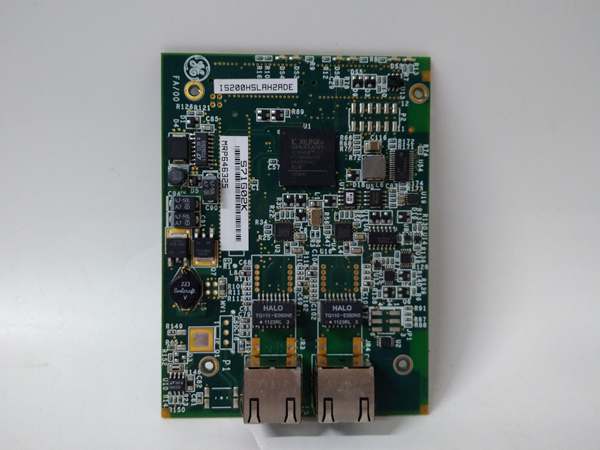
- Status Handshaking: Green/Red LEDs on the faceplate provide real-time link status. If the fiber is severed or the connector is dirty, the link drops instantly, triggering a hardware fault on the controller to prevent running blind.
Field Service Pitfalls: What Rookies Get Wrong
Violating the Fiber Optic Bend Radius
A rookie is dressing the LC fiber patch cords in the cable tray. He pulls the excess slack tight around a 90-degree angle bracket to make it look “neat and tidy.” The bend radius goes below the 1-inch minimum. The light waves leak out of the cladding, the link drops, and the turbine trips on “HSSL Loss.”
- Field Rule: Never bend fiber tighter than a sharpie marker (approx. 1-inch radius). Leave a generous service loop (6-8 inches) at both ends of the cable run. A crushed fiber is a dead fiber.
Ignoring the LC Connector Ferrule Cleanliness
A mechanic swaps a failed HSLA card. He grabs a dusty, unboxed fiber patch cord from the bottom of his tool bag and plugs it straight into the LC port. Microscopic dust motes on the ferrule scatter the laser light. The optical power budget drops below the receiver’s sensitivity threshold, causing intermittent “CRC Errors” and packet drops.
- Quick Fix: Always carry fiber optic cleaning pens or lint-free wipes with isopropyl alcohol. Visually inspect the LC connector tip with a microscope if available. A speck of dust is all it takes to sever your communication lifeline.
Using the Wrong Generation SFP/Transceiver
A junior engineer tries to save money by cannibalizing a generic 100Base-FX SFP module from an old networking switch and forcing it onto the HSLA board. The wavelength (1310nm vs 850nm) and optical budget don’t match the GE proprietary HSSL standard. The link never comes up, and he spends 4 hours blaming the software configuration.
- Field Rule: Only use factory-specified or GE-approved transceivers for HSSL links. Do not mix and match commercial off-the-shelf networking gear with GE proprietary excitation hardware. The optical physics don’t translate.
Commercial Availability & Pricing Note
Please note: The listed price is for reference only and is not binding. Final pricing and terms are subject to negotiation based on current market conditions and availability.


