
Description
Key Technical Specifications
-
Model Number: IS200GDDDG1ABA
-
Manufacturer: General Electric (Salem, VA)
-
Logic Voltage: +5 V @ 1.2 A, ±12 V @ 200 mA from VME back-plane
-
Gate Drive: 6 × 15 V differential, 2 A peak, 20 µs width, transformer-isolated
-
Dynamic Discharge: On-board 600 V IGBT with 2 kA pulse capability, 10 µs turn-on
-
Isolation: 1500 Vrms gate-to-logic, 500 V channel-to-channel
-
Connectors: 96-pin DIN VME, two 20-position pluggable for gate/discharge cables
-
Protection: Gate-supply UVLO, desat detection, 39 V MOV per channel
-
Diagnostics: 3 LEDs (DS100-DS102) for gate fault, discharge status, logic OK
-
Operating Temperature: –30 °C to +65 °C (conformal-coated)
-
Dimensions: 220 × 160 × 90 mm, 2.3 kg
IS200GDDDG1ABA
Field Application & Problem Solved
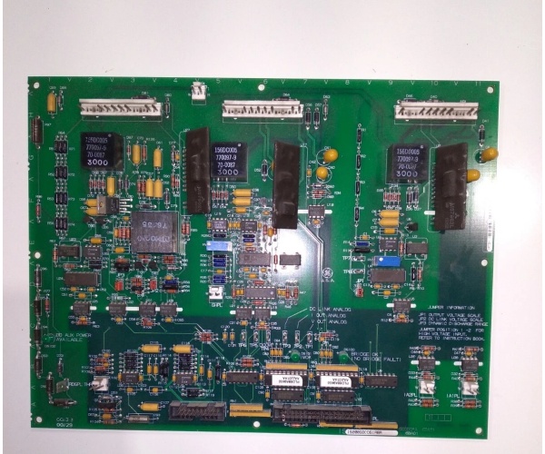
A frame-9 combined-cycle block running an EX2100 static exciter doesn’t shut down gracefully by magic—it dumps the DC link into a resistor bank in < 10 µs. The IS200GDDDG1ABA is the card that makes that happen. It sits in the VME rack, receives gate-timing words from the Mark VI CPU, and spits out six 15 V gate pulses to the IGBT bridge; when the unit trips it turns on the on-board 600 V IGBT to dump the link energy into the brake resistor. When the card fails you lose either gate drive (bridge collapses) or discharge (link over-volts), both trip the unit on “BRIDGE FAULT”; swap the card, snap the 20-pin plugs back in, and the bridge comes back smooth—no re-cal, no firmware flash. You’ll find this PCB in every EX2100 cabinet from 50 MW peakers to 400 MW combined-cycle blocks. Its value is speed: the on-board IGBT can sink 2 kA for 100 ms, fast enough to protect the bridge diodes from over-volt when the grid breaker opens.
A frame-9 combined-cycle block running an EX2100 static exciter doesn’t shut down gracefully by magic—it dumps the DC link into a resistor bank in < 10 µs. The IS200GDDDG1ABA is the card that makes that happen. It sits in the VME rack, receives gate-timing words from the Mark VI CPU, and spits out six 15 V gate pulses to the IGBT bridge; when the unit trips it turns on the on-board 600 V IGBT to dump the link energy into the brake resistor. When the card fails you lose either gate drive (bridge collapses) or discharge (link over-volts), both trip the unit on “BRIDGE FAULT”; swap the card, snap the 20-pin plugs back in, and the bridge comes back smooth—no re-cal, no firmware flash. You’ll find this PCB in every EX2100 cabinet from 50 MW peakers to 400 MW combined-cycle blocks. Its value is speed: the on-board IGBT can sink 2 kA for 100 ms, fast enough to protect the bridge diodes from over-volt when the grid breaker opens.
Installation & Maintenance Pitfalls (Expert Tips)
Gate leads reversed—bridge shorts on power-up
The two 20-pin headers are keyed alike but pin-outs alternate phase-to-phase. Land G1 on G2 and you fire the wrong IGBT pair—bridge crowbars, fuse blows, unit trips. Always ring-out gate leads with a DMM before you energize; you should see 12 Ω primary, not a dead short.
The two 20-pin headers are keyed alike but pin-outs alternate phase-to-phase. Land G1 on G2 and you fire the wrong IGBT pair—bridge crowbars, fuse blows, unit trips. Always ring-out gate leads with a DMM before you energize; you should see 12 Ω primary, not a dead short.
Desat resistor drift—false “GATE FLT” every week
A 2.2 kΩ desat resistor sets the IGBT Vce fault level. After 10 years the resistor drifts high; the card thinks the IGBT is saturating and flags false faults. If you see weekly gate faults but the bridge is healthy, swap the resistor or the whole card—gate drive is not field-repairable.
A 2.2 kΩ desat resistor sets the IGBT Vce fault level. After 10 years the resistor drifts high; the card thinks the IGBT is saturating and flags false faults. If you see weekly gate faults but the bridge is healthy, swap the resistor or the whole card—gate drive is not field-repairable.
Dynamic-discharge IGBT short—link won’t charge
The on-board 600 V IGBT can short if a surge hits the link. If the DC bus sits at 0 V and the charger current folds back, meter C-E of the discharge IGBT—if it’s 0 Ω, the card is scrap. Keep a spare on the shelf; GE doesn’t sell the IGBT separate.
The on-board 600 V IGBT can short if a surge hits the link. If the DC bus sits at 0 V and the charger current folds back, meter C-E of the discharge IGBT—if it’s 0 Ω, the card is scrap. Keep a spare on the shelf; GE doesn’t sell the IGBT separate.
Missing nylon washer—card arcs to rack
The four corner holes are through-plated. Forget the fiber washers and the card edge sits 0.5 mm proud; 125 V link voltage finds the rack paint, arcs, and blows a hole in the ground plane. Use the original GE shoulder washers—torque to 8 in-lb, no more.
The four corner holes are through-plated. Forget the fiber washers and the card edge sits 0.5 mm proud; 125 V link voltage finds the rack paint, arcs, and blows a hole in the ground plane. Use the original GE shoulder washers—torque to 8 in-lb, no more.
IS200GDDDG1ABA
Technical Deep Dive & Overview
IS200GDDDG1ABA is a dual-function board frozen in 2000 IGBT technology. One half is a six-channel gate-drive amplifier: a 32-channel FPGA converts VME timing words into 15 V differential pulses; gate-drive transformers provide 1500 V isolation. The other half is a 600 V, 2 kA dynamic-discharge IGBT with millisecond-speed desat detection. Because both functions live on the same card you can swap it hot and the exciter never knows—just kill the 125 VDC link first or you’ll arc-weld the 20-pin plugs. Treat the gate leads like spark-plug wires and the discharge IGBT like a lightning bolt in a can—the board will keep the DC link alive for another thirty years
IS200GDDDG1ABA is a dual-function board frozen in 2000 IGBT technology. One half is a six-channel gate-drive amplifier: a 32-channel FPGA converts VME timing words into 15 V differential pulses; gate-drive transformers provide 1500 V isolation. The other half is a 600 V, 2 kA dynamic-discharge IGBT with millisecond-speed desat detection. Because both functions live on the same card you can swap it hot and the exciter never knows—just kill the 125 VDC link first or you’ll arc-weld the 20-pin plugs. Treat the gate leads like spark-plug wires and the discharge IGBT like a lightning bolt in a can—the board will keep the DC link alive for another thirty years
.


