
Description
Hard-Numbers: Technical Specificiations
- Wetting Supply Voltage: 70 VDC (range: 63V to 84V DC)
- Plug Connector Count: 8 connectors (12, 9, 6, 4, 3, and 2-position variants)
- Contactor Drivers: K41 (Close), K53A/B (Flash), KDEP (De-Excitation)
- EMIO Interface: Three 25-pin connectors (J505→M1, J508→M2, J515→C)
- Operating Temperature: -20°C to +70°C
- Isolation Rating: 1500V AC (primary to secondary circuits)
- Mounting Location: Exciter Power Backplane Rack (EPBP)
- Diagnostic LEDs: None (blind module—relies on EMIO feedback)
- Heat Sink: Single aluminum finned heatsink (integrated)
- Contact Wetting Current: 5-10 mA (maintains clean contact closure)
The Real-World Problem It Solves
You’re troubleshooting a 9FA gas turbine that tripped on “Field Flashing Failure” during a black start. The old relay driver card’s wetting voltage sagged to 50VDC under load, causing the K53A flash relay to chatter and fail to close. Without a clean field flash pulse, the generator excitation never builds, leaving you dead in the water during a critical restart. You need a hardened driver that can push consistent 70VDC wetting current through oxidized contacts and drive high-current DC contactors without blinking. This EXHS board eliminates that nightmare. It acts as the muscle behind your field flashing and de-excitation sequences, ensuring every contactor closes hard and stays closed until the sequence completes.
Where you’ll typically find it:
- EX2100/EX2100e Exciter Cabinets: Mounted on the EPBP backplane, driving K41 close contactor, K53A/B flash relays, and KDEP de-excitation relay.
- Black Start & Emergency Standby Units: Critical for units requiring reliable field flashing from dead-bus conditions.
- Retrofit Projects: Replacing aged relay driver cards in legacy EX2100 systems showing wetting voltage drift and contactor chatter.
It turns a temperamental, voltage-sagging relay driver into a rock-solid, deterministic contact closure machine.
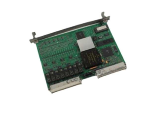
GE IS200EXHSG2A
Hardware Architecture & Under-the-Hood Logic
This board isn’t a processor—it’s a brute-force relay driver with precision wetting current control. It lives on the EPBP backplane, acting as the muscle behind your most critical excitation sequences. The “G2A” suffix indicates enhanced current handling capability and optimized trace routing for high-current DC contactor applications.
- 70VDC Wetting Supply Acquisition: The board receives 70VDC from the station battery bus via terminals J12M1 and J12M2. Precision current-limiting resistors deliver a steady 5-10mA wetting current to each monitored contact (K41, K53A, K53B, KDEP).
- Contactor Drive Circuitry: When commanded by the EMIO, the EXHS activates high-current driver transistors. These deliver the full 70VDC wetting voltage to the contactor coils, forcing K41 (close), K53A/B (flash), or KDEP (de-excitation) to slam shut with authority.
- Feedback Signal Conditioning: The board monitors the actual state of each contactor via auxiliary contacts powered by the 70VDC wetting supply. It conditions these feedback signals and routes them back to the EMIO through the 25-pin connectors (J505, J508, J515).
- Multi-Controller Distribution: In redundant configurations, feedback signals are distributed across M1, M2, and C controllers. The J515 connector (C controller path) carries contactor status but notably excludes de-excitation and crowbar signals, maintaining proper redundancy segregation.
Field Service Pitfalls: What Rookies Get Wrong
Running the 70VDC Wetting Supply Through Undersized Wire
A rookie lands the 70VDC wetting supply to the EXHS using #18 AWG wire from a leftover spool. During a field flash sequence, the K53A relay draws 8 amps through the coil. The undersized wire drops 4 volts, reducing the wetting voltage to 66VDC. The relay chatters, the flash fails, and the turbine won’t synchronize.
- Field Rule: Use minimum #14 AWG (2mm²) stranded copper wire for the 70VDC wetting supply. Crimp on heavy-duty compression lugs rated for 15 amps continuous. Verify the voltage at the EXHS terminals under load—it must stay within 63-84VDC range.
Swapping a G2A Into a Single-Contactor Application
A junior engineer replaces a failed IS200EXHSG1A with a warehouse-stock IS200EXHSG2A. The G2A expects a dual-contactor configuration (K41 and /B both present), but the plant only has a single K41 contactor. The EXHS2A’s self-test logic detects the missing /B feedback and flags a permanent fault, blocking all contactor operations.
- Quick Fix: Verify the exact contactor configuration before ordering a replacement. The G2A variant is designed for applications with multiple contactors (K41 + /B). If your system only uses K41, you need the G1A variant. Don’t force a multi-contactor driver into a single-contactor slot.
Ignoring the Heat Sink’s Airflow Requirements
A mechanic installs the EXHS board in a crowded EPBP rack with zero clearance above the heatsink. During a prolonged field flash sequence, the K41 contactor draws heavy current for 30 seconds. The EXHS’s driver transistors overheat, thermally throttle, and drop the wetting voltage below 60VDC. The contactor releases prematurely, aborting the flash sequence.
- Field Rule: Maintain minimum 2-inch clearance above the EXHS heatsink. Ensure forced-air ventilation flows across the fins. Touch the heatsink after a contactor operation—if it’s too hot to hold for 3 seconds, your airflow is inadequate. In high-duty-cycle applications, consider adding a dedicated 24VDC muffin fan blowing across the rack.
Commercial Availability & Pricing Note
Please note: The listed price is for reference only and is not binding. Final pricing and terms are subject to negotiation based on current market conditions and availability.


