
Description
Key Technical Specifications
-
Model Number: IS200EXCSG1A
-
Manufacturer: General Electric (Salem, VA)
-
Power Supply: +12 VDC ±5 % @ ≤ 0.3 W (supplied by EGPA card)
-
Signal Output: Differential logic: High > 11 V, Low < 1.2 V, 4-pin P1 connector
-
Sensors: 2 × unidirectional Hall-effect devices mounted opposite each other for bidirectional current detection
-
Flux Concentration: Gapped steel rings slipped over bus bar; PCB bolts to same bar—no external shunt required
-
Isolation: 1500 Vrms sensor-to-logic; board lives at bus potential, signals are magnetically coupled
-
Operating Temperature: –40 °C to +70 °C (conformal-coated)
-
Dimensions / Weight: 160 × 110 × 46 mm, 0.4 kg
-
Redundancy: Three boards per bridge (one per bus leg); EGPA filters and ORs outputs before sending to EMIO
.

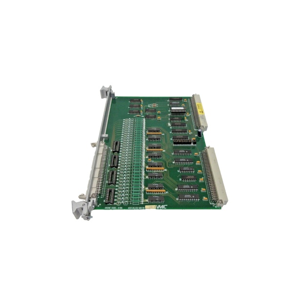
GE VMIVME-2120
Field Application & Problem Solved
In an EX2100 bridge cabinet you can’t trust a gate pulse alone—you want proof the silicon actually carried current. Mount the IS200EXCSG1A directly on the DC bus bar; when current flows the Hall devices see the flux in the steel rings and yank the output low. Lose that feedback and the Mark VI trips on “CONDUCTION FAIL,” because a misfiring SCR will blow the fuse or cook the snubber. Swap the card and you’re back to real-time proof-of-current without re-calibrating a single parameter. Found on every bus leg in 50 MW peakers up to 400 MW combined-cycle blocks; its value is bullet-proof redundancy—if one sensor fails the second still pulls the line low, so the exciter keeps running while you plan the next outage.
In an EX2100 bridge cabinet you can’t trust a gate pulse alone—you want proof the silicon actually carried current. Mount the IS200EXCSG1A directly on the DC bus bar; when current flows the Hall devices see the flux in the steel rings and yank the output low. Lose that feedback and the Mark VI trips on “CONDUCTION FAIL,” because a misfiring SCR will blow the fuse or cook the snubber. Swap the card and you’re back to real-time proof-of-current without re-calibrating a single parameter. Found on every bus leg in 50 MW peakers up to 400 MW combined-cycle blocks; its value is bullet-proof redundancy—if one sensor fails the second still pulls the line low, so the exciter keeps running while you plan the next outage.
Installation & Maintenance Pitfalls (Expert Tips)
Wrong orientation—sensor faces air, output stays high, false trip
The Hall devices are unidirectional; mount the board so the arrow on the silk-screen points in the direction of positive power flow. Flip it 180° and the flux never reaches threshold—EGPA sees no conduction and trips the bridge. Use the witness arrow stamped on the bus bar; if it’s missing, megger the cable and confirm current direction before you bolt down.
The Hall devices are unidirectional; mount the board so the arrow on the silk-screen points in the direction of positive power flow. Flip it 180° and the flux never reaches threshold—EGPA sees no conduction and trips the bridge. Use the witness arrow stamped on the bus bar; if it’s missing, megger the cable and confirm current direction before you bolt down.
Gapped rings mis-aligned—flux bypasses sensor, intermittent fault
The steel rings must straddle the bus with the 2 mm air-gap centered over the sensors. If the plastic bracket cracks or the rings lift, flux leaks and the output flickers. Torque the bracket screws to 1 N·m and check the gap with a feeler—0.05 mm variance is enough to drop the signal below 1.2 V.
The steel rings must straddle the bus with the 2 mm air-gap centered over the sensors. If the plastic bracket cracks or the rings lift, flux leaks and the output flickers. Torque the bracket screws to 1 N·m and check the gap with a feeler—0.05 mm variance is enough to drop the signal below 1.2 V.
12 V supply missing—board looks dead, exciter folds to manual
Power comes from EGPA on P1-1 (+12 V) and P1-2 (return). If the EGPA fuse opens the board pulls the output high (> 11 V) and EMIO thinks the bridge is not conducting. Meter 12 V at P1 before you blame the Hall sensor—five-minute fuse swap beats a crane call.
Power comes from EGPA on P1-1 (+12 V) and P1-2 (return). If the EGPA fuse opens the board pulls the output high (> 11 V) and EMIO thinks the bridge is not conducting. Meter 12 V at P1 before you blame the Hall sensor—five-minute fuse swap beats a crane call.
Conformal coat cracked—salt fog bridges the output, fake low
The board is coated, but the 4-pin edge is masked. If the coat cracks, salt bridges the open-collector output to ground and you get a permanent “conduction” flag. Scrape the salt, hit the edge with 2100-FTG, and re-coat—problem gone for another decade.
The board is coated, but the 4-pin edge is masked. If the coat cracks, salt bridges the open-collector output to ground and you get a permanent “conduction” flag. Scrape the salt, hit the edge with 2100-FTG, and re-coat—problem gone for another decade.
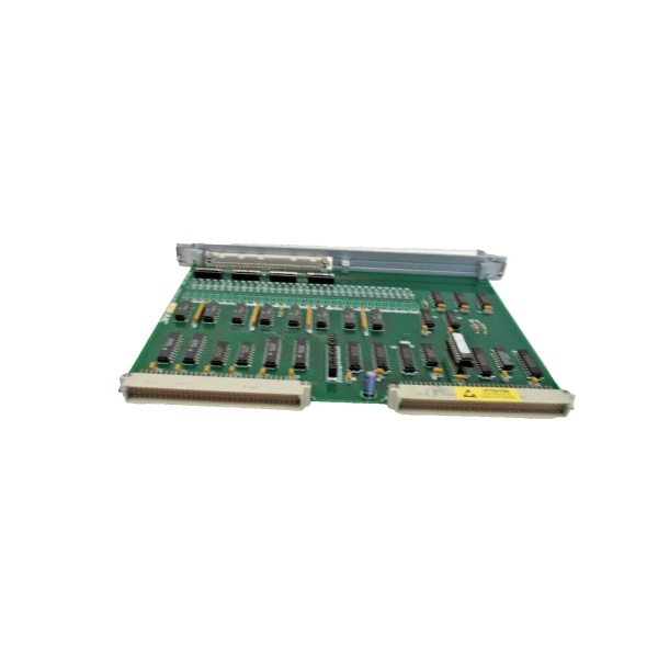
GE VMIVME-2120
Technical Deep Dive & Overview
IS200EXCSG1A is a passive Hall-effect switch frozen in 2000 silicon. Two sensors sit in gapped steel rings bolted to the bus bar; when flux exceeds the operate point the open-collector output pulls low, giving EGPA real-time proof the silicon actually carried current. Because the card is magnetically coupled you can swap it hot—just kill the 12 V supply first or you’ll back-feed the Hall devices. Treat the steel rings like a current transformer core and the board will keep the bridge honest for another thirty years
IS200EXCSG1A is a passive Hall-effect switch frozen in 2000 silicon. Two sensors sit in gapped steel rings bolted to the bus bar; when flux exceeds the operate point the open-collector output pulls low, giving EGPA real-time proof the silicon actually carried current. Because the card is magnetically coupled you can swap it hot—just kill the 12 V supply first or you’ll back-feed the Hall devices. Treat the steel rings like a current transformer core and the board will keep the bridge honest for another thirty years
.


