
Description
Hard-Numbers: Technical Specificiations
- Input Voltage Range: 120 VAC to 13,000 VAC (RMS, Phase-to-Ground)
- Scaled Output Signal: 1.5 VAC to 15 VAC (Linear proportional attenuation)
- Attenuation Ratios: 80:1, 160:1, 320:1, or 640:1 (selectable via DIP switches)
- Isolation Rating: 2500 VAC (Primary High-Voltage to Secondary Logic)
- Frequency Tracking: 47 Hz to 63 Hz
- Operating Temperature: -40°C to +70°C
- Mounting Location: High-Voltage Interface (HBI) Rack or Auxiliary Cabinet
- Connector Types: Barrier Terminal Strips (HV input), IDC Header (LV output)
- Diagnostic LEDs: Input Signal Valid, Output Signal Valid, Fault Latch
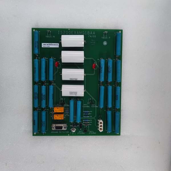
GE IS200EXAMG1BAA
The Real-World Problem It Solves
You’re troubleshooting a coastal 9FA gas turbine that keeps tripping on “Generator Overexcitation” during midnight storms. The standard attenuator board can’t reject the massive electrical hash caused by nearby lightning strikes and the 4160V switchgear arcing. The DSPX processor is seeing phantom voltage spikes, causing the AVR to hunt wildly and eventually trip the unit. You need a board that has been hardened with additional EMI shielding and custom firmware filtering. This “BZZ” variant eliminates that nightmare. It provides a deterministic, noise-immune, perfectly scaled feedback loop to keep your excitation rock solid when the weather turns nasty.
Where you’ll typically find it:
- EX2100/Mark VI Auxiliary Cabinets (HBI Rack): Sitting right next to the Potential Transformers (PTs) in high-EMI environments.
- Coastal & Offshore Platforms: Where salt spray and high humidity threaten the dielectric integrity of standard control boards.
- Retrofit Projects with Non-Standard PT Ratios: Requiring custom scaling factors that standard off-the-shelf boards can’t handle.
It turns a noisy, drifting high-voltage feedback loop into a precise, deterministic, and perfectly scaled signal for your excitation control.
Hardware Architecture & Under-the-Hood Logic
This isn’t a passive resistor ladder; it’s a precision measurement instrument wrapped in military-grade shielding. It lives in the HBI rack, acting as the ultimate bodyguard between the high-voltage grid and your sensitive DSPX processor. The “BZZ” suffix indicates a project-specific build with enhanced conformal coating, additional ground planes, and custom firmware filtering for mission-critical deployments.
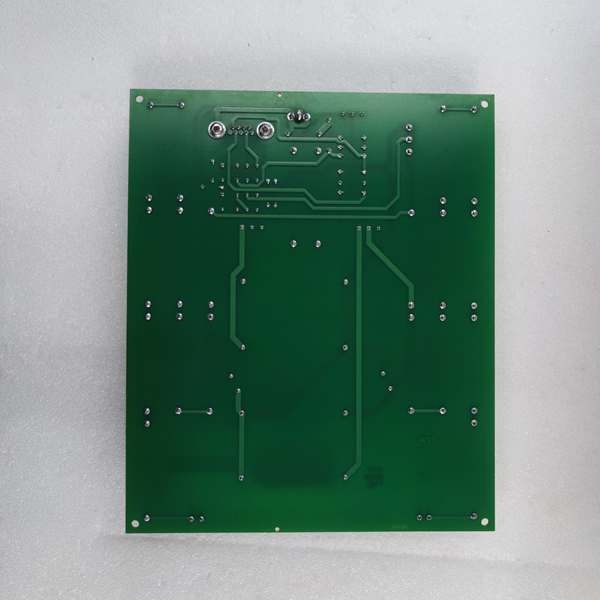
- High-Voltage Input Acquisition: Thick-gauge, high-voltage wire lands on the barrier terminal strips. The raw voltage from the Potential Transformer (PT) enters the board’s primary side, immediately encountering a heavy-duty surge arrestor.
- Precision Resistive Attenuation & Filtering: Based on your DIP switch settings, a precision high-voltage resistor network divides the incoming voltage. Before exiting the primary side, the signal passes through a bank of custom-tuned RC filters designed to scrub the specific frequency harmonics present in your plant’s grid.
- Galvanic Isolation & Buffered Output: A high-dielectric isolation barrier completely severs the electrical connection between the primary and secondary sides. An active buffering op-amp stage reconstructs the sine wave, ensuring zero phase shift and perfect linearity.
- Low-Voltage Output to Backplane: The conditioned, attenuated, and noise-free signal is routed through a heavy-duty IDC header to the backplane, where it travels to the DSPX processor for real-time calculation of generator terminal voltage.
GE IS200EXAMG1BAA
Field Service Pitfalls: What Rookies Get Wrong
Assuming “BZZ” is Interchangeable with Standard “B” Boards
A rookie pulls a failed IS200EXAMG1BZZ and swaps it with a standard IS200EXAMG1B from the central warehouse. The turbine powers up, but the AVR keeps hunting. The standard board lacks the custom firmware filtering and modified zero-offset calibration required for this specific plant’s 13.8kV grid configuration. The DSPX sees a permanent 2% voltage error, leading to unstable VAR control.
- Field Rule: Never substitute a standard board for a “BZZ” (or any double/triple suffix) variant. These are project-specific builds. Order the exact OEM part number. Attempting to use a generic spare will lead to hours of pointless AVR tuning and eventual process instability.
Stripping the Barrier Strip Screws on the High-Voltage Side
A junior engineer is tightening the 13.8kV PT input wires onto the EXAM’s barrier strip. He uses a cheap, ill-fitting #2 Phillips screwdriver. The screw head strips, so he cranks down harder with a pair of pliers. He deforms the brass terminal, creating a high-resistance joint. During the next lightning storm, the weak point arcs over, vaporizing the terminal block and blowing the 13.8kV station service transformer.
- Quick Fix: Always use a properly sized, high-quality screwdriver that fits the head snugly. Apply steady, increasing torque until the wire is secure. If a screw head strips, replace the entire barrier strip immediately—do not try to salvage it with pliers.
Touching the Board Immediately After LOTO Removal
A mechanic performs LOTO on the PT supply and waits 5 minutes. He removes the lockout tags, reaches into the HBI rack, and grabs the EXAM board to pull it. Unbeknownst to him, a failed MOV (Metal Oxide Varistor) on the input side has shorted the 120VAC auxiliary supply directly to the chassis. The board is still energized at 120VAC. He gets a nasty shock, blows the board to pieces, and knocks himself unconscious against the 4160V bus duct.
- Field Rule: Never assume a board is de-energized just because the upstream breaker is off. Verify zero energy with a high-voltage probe at the input terminals of the EXAM before touching it. A shorted surge suppressor can keep a board lethally hot long after the main supply is cut.
Commercial Availability & Pricing Note
Please note: The listed price is for reference only and is not binding. Final pricing and terms are subject to negotiation based on current market conditions and availability.


