
Description
Hard-Numbers: Technical Specificiations
- Input Voltage Range: 120 VAC to 13,000 VAC (RMS, Phase-to-Ground)
- Scaled Output Signal: 1.5 VAC to 15 VAC (Linear proportional attenuation)
- Attenuation Ratios: 80:1, 160:1, 320:1, or 640:1 (selectable via DIP switches)
- Isolation Rating: 2500 VAC (Primary High-Voltage to Secondary Logic)
- Frequency Tracking: 47 Hz to 63 Hz
- Operating Temperature: -40°C to +70°C
- Mounting Location: High-Voltage Interface (HBI) Rack or Auxiliary Cabinet
- Connector Types: Barrier Terminal Strips (HV input), IDC Header (LV output to backplane)
- Diagnostic LEDs: Input Signal Valid, Output Signal Valid, Fault Latch
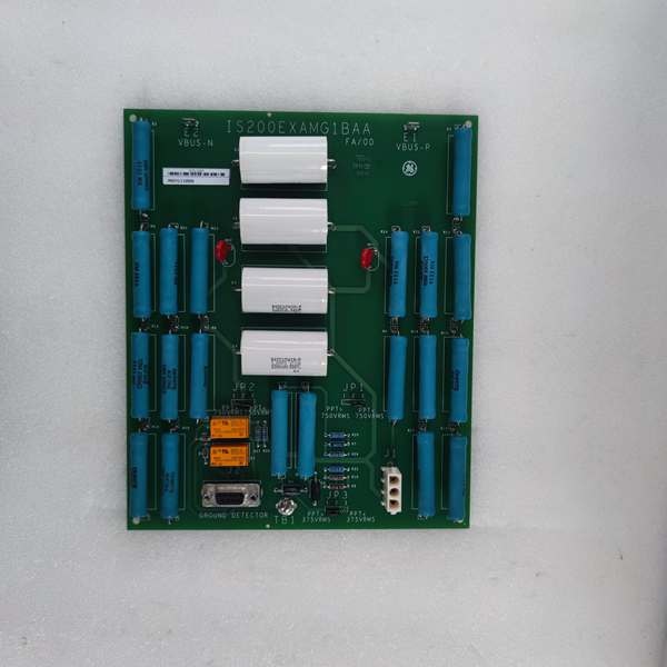
GE IS200EXAMG1BAA
The Real-World Problem It Solves
You’re troubleshooting a 9FA gas turbine that’s experiencing random “Generator Overexcitation” trips. The old, hand-wired voltage divider network in the HBI rack has drifted by 15% due to decades of thermal cycling. The DSPX processor thinks the generator terminal voltage is 20kV when it’s actually 18.5kV, causing the AVR to hunt and eventually trip the unit. You need a precision attenuator that can take a potentially lethal 13,000VAC input, knock it down to a safe 1.5V-15V signal range, and feed it cleanly to the DSPX without any phase shift. This EXAM board eliminates that nightmare. It provides a deterministic, isolated, and highly accurate voltage feedback loop to keep your AVR rock solid.
Where you’ll typically find it:
- EX2100/Mark VI Auxiliary Cabinets (HBI Rack): Sitting right next to the Potential Transformers (PTs), scaling the raw grid voltage for the excitation system.
- Retrofit Projects: Replacing archaic, drifting resistor-divider banks in legacy turbine control rooms to eliminate AVR hunting.
- High-Voltage Switchgear Compartments: Providing a critical safety barrier between the 13.8kV primary side and the 24VDC control logic.
It turns a lethal, noisy high-voltage wild west into a precise, deterministic, and perfectly scaled feedback loop for your excitation control.
Hardware Architecture & Under-the-Hood Logic
This isn’t a passive resistor ladder; it’s a precision measurement instrument built to survive the brutal electrical environment right next to a multi-kilovolt transformer. It lives in the HBI rack, acting as the ultimate bodyguard between the high-voltage grid and your sensitive DSPX processor. The “BAA” suffix indicates RoHS 6/6 lead-free manufacturing and optimized component selection for enhanced dielectric strength.
- High-Voltage Input Acquisition: Thick-gauge high-voltage wire lands on the barrier terminal strips. The raw voltage from the Potential Transformer (PT) enters the board’s primary side.
- Precision Resistive Attenuation: Based on your DIP switch settings (which dictate the 80:1 to 640:1 ratio), a precision high-voltage resistor network divides the incoming voltage down to a manageable level.
- Galvanic Isolation & Signal Conditioning: A high-dielectric isolation barrier completely severs the electrical connection between the primary high-voltage side and the secondary low-voltage side. Active buffering circuitry cleans up the signal, removing noise and ensuring a pure sine wave.
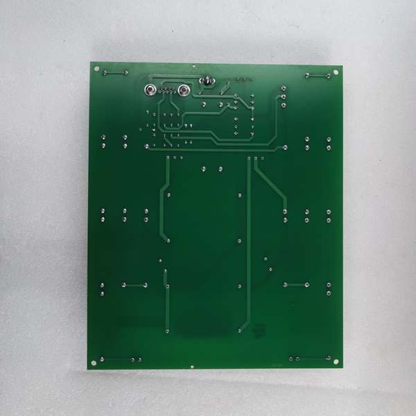
- Low-Voltage Output to Backplane: The conditioned, attenuated signal is routed through a heavy-duty IDC header to the backplane, where it travels to the DSPX processor for real-time calculation of generator terminal voltage.
GE IS200EXAMG1BAA
Field Service Pitfalls: What Rookies Get Wrong
Mismatching DIP Switch Settings to Actual PT Ratios
A rookie replaces a failed EXAM. He looks at the old board, sees the DIP switches set to Ratio 160:1, and copies them exactly. What he didn’t know is that the plant swapped the 120V PTs for 240V PTs two years ago. The EXAM now over-reports the voltage by 100%. The DSPX sees a fake overvoltage condition and instantly trips the turbine, costing the plant $200K in lost generation.
- Field Rule: Never blindly copy DIP switches. Physically verify the PT primary-to-secondary ratio stamped on the nameplate. Calculate the required attenuation ratio based on your maximum system voltage. Double-check your math with the GE manual’s lookup table before flipping the first switch.
Attempting to Rework Lead-Free (RoHS) Solder Joints in the Field
A mechanic notices a cold solder joint on a high-voltage resistor and decides to touch it up with his standard 63/37 leaded solder iron set to 350°C. The lead-free solder on the “BAA” board has a much higher melting point. He cranks the iron to 420°C, delaminates the PCB trace, and utterly destroys the board’s dielectric isolation layer. The next time the turbine syncs, 13kV jumps the gap and fries the entire HBI rack.
- Field Rule: Never attempt to solder or rework RoHS 6/6 hardware in the field. These boards require specialized lead-free solder paste and precise temperature profiles. If you spot a physical defect, RMA the board to a certified repair center. You are not equipped to fix it in a turbine cabinet.
Disconnecting HV Wires While the Grid is Live
An overconfident junior engineer decides to “quick-swap” the EXAM while the generator is synchronized to the grid to minimize downtime. He reaches into the HBI rack and yanks the 240VAC PT input wires without shutting down the excitation system. A massive inductive voltage spike arcs across the barrier strip, instantly vaporizing the EXAM’s input stage and blowing the 13.8kV station service transformer.
- Field Rule: Always follow strict Lockout/Tagout (LOTO) procedures for the PT supply before touching any high-voltage wiring. Wait a minimum of 5 minutes for filter capacitors to discharge. Verify 0V at the barrier strip with a high-voltage probe. High-voltage doesn’t care about your production targets.
Commercial Availability & Pricing Note
Please note: The listed price is for reference only and is not binding. Final pricing and terms are subject to negotiation based on current market conditions and availability.


