
Description
Hard-Numbers: Technical Specificiations
- Input Voltage Range (Field Bus): 125 VDC to 1000 VDC
- Input Voltage Range (PPT): 120 VAC to 1300 VAC (RMS)
- Scaled Output Signal: 50 VAC Square Wave
- Scaling Ratios: Programmable via JP1 & JP2 Jumpers (<750V / >750V)
- Operating Temperature: -40°C to +70°C
- Isolation Rating: High Voltage Isolation (Field Bus to Logic)
- Mounting Location: HBI Module (Auxiliary Cabinet)
- Connectors: J1, J2, Ground Detector Port
- Diagnostic LEDs: None (Blind module, relies on EGDM status)
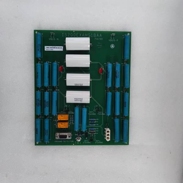
GE IS200EXAMG1B
The Real-World Problem It Solves
You are troubleshooting a 9FA gas turbine that keeps tripping on “Rotor Ground Fault,” but the EGDM module is reporting “Open Circuit” on the sense resistor, meaning you have absolutely no idea where the fault is. The raw generator field voltage sits at a lethal 800VDC. If you tried to pipe that directly into a standard 24VDC control card, you would vaporize the EGDM and likely start a fire. You need a sacrificial lamb that can eat those high voltages, scale them down to a harmless 50VAC square wave, and feed them cleanly to the EGDM. This EXAM board eliminates that nightmare. It acts as the high-voltage interface between the brutal electrical environment of the generator rotor and the sensitive ground fault detection logic.
Where you’ll typically find it:
- EX2100/Mark VI Auxiliary Cabinets: Mounted inside the High Voltage Interface (HBI) module near the static exciter or rotating diode bridge.
- Alterrex Excitation Systems: Requires two EXAM modules (one for generator field, one for exciter field) working in tandem.
- Retrofit Projects: Replacing ancient, hand-wired voltage divider networks that drifted out of calibration decades ago.
It turns a lethal, unmeasurable high-voltage field bus into a deterministic, low-voltage signal path for precise ground fault location.
Hardware Architecture & Under-the-Hood Logic
This isn’t a processor; it is a precision voltage divider and signal conditioner designed to sit right next to the 4160V bus. It lives in the HBI module, acting as the eyes and ears of the EGDM ground detector. The “G1B” suffix indicates enhanced trace routing and improved EMI filtering for better performance in electrically noisy switchgear compartments.
- High-Voltage Acquisition: Thick-gauge cables land on the EXAM’s high-voltage terminals, carrying the raw output from the generator field winding or the Power Potential Transformer (PPT).
- Jumper-Selected Attenuation: Based on whether your PPT voltage is above or below 750VAC (determined by JP1 and JP2 jumpers), the EXAM engages a specific resistive voltage divider network. It chops the massive input voltage down to a precise, usable level.
- Square Wave Injection & Sense Resistor Interface: The active Master DSPX sends a 50VAC square wave to the EXAM. The EXAM applies this signal to one end of the EGDM’s sense resistor. It then reads the voltage drop across that resistor to calculate the ground path resistance.
- Signal Transmission to EGDM: The attenuated voltage signal is carried over a 9-pin cable to the EGDM module sitting on the ERBP backplane. The EGDM analyzes this signal to pinpoint the exact location of a rotor ground fault.
GE IS200EXAMG1B
Field Service Pitfalls: What Rookies Get Wrong
Setting Jumpers JP1/JP2 Based on Guesswork
A rookie is replacing a failed EXAM. He looks at the PPT input terminals, sees “660VAC” written on the nameplate, and sets the jumpers for “>750V.” Unknown to him, that nameplate is from a previous retrofit; the actual operating voltage is only 480VAC. The EXAM over-attenuates the signal. The EGDM can’t detect the square wave properly and throws a permanent “Ground Detector Malfunction” alarm.
- Field Rule: Never guess the jumper settings. Measure the actual RMS operating voltage of the PPT using a true-RMS multimeter. Set JP1 and JP2 according to the manual’s threshold (typically 750VAC). If you’re swapping a board, photograph the old jumpers before removal.
Running Low-Voltage Signal Cables Parallel to HV Bushings
A mechanic is routing the 9-pin cable from the EXAM to the EGDM. To save time, he zip-ties it directly to the 4160V generator bus duct for 20 feet. The sheer electromagnetic field radiating from the bus duct induces massive common-mode noise into the 50VAC signal. The EGDM interprets the noise as a massive ground fault and trips the turbine.
- Quick Fix: Route the EXAM-to-EGDM cable using shielded twisted pair (STP). Keep the cable at least 12 inches away from any high-voltage bus work or transformer tanks. Ground the shield drain wire at the EGDM terminal end only. A floating shield is an antenna for spurious trips.
Touching the Board Before Discharging the PPT Capacitors
An arrogant young tech decides to “hot-swap” a suspected bad EXAM. He pulls the 24VDC control power but ignores the 660VAC PPT inputs. He reaches into the HBI rack and grabs the board. The PPT’s filter capacitors are still holding a 400V charge. He gets the shock of his life, blows the EXAM to smithereens, and takes the EGDM down with it via the 9-pin cable.
- Field Rule: Treat the HBI rack like a live substation. Lock out and tag out the PPT supply. Wait a minimum of 5 minutes for the capacitors to discharge. Use a high-voltage probe to verify 0V at the EXAM terminals before touching a single component. High voltage doesn’t care about your deadlines.
Commercial Availability & Pricing Note
Please note: The listed price is for reference only and is not binding. Final pricing and terms are subject to negotiation based on current market conditions and availability.


