
Description
System Architecture & Operational Principle
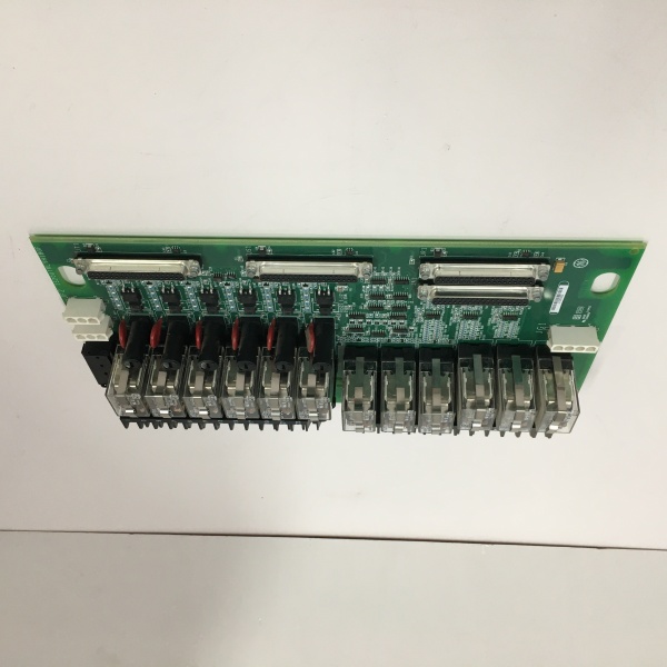
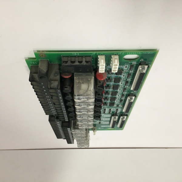
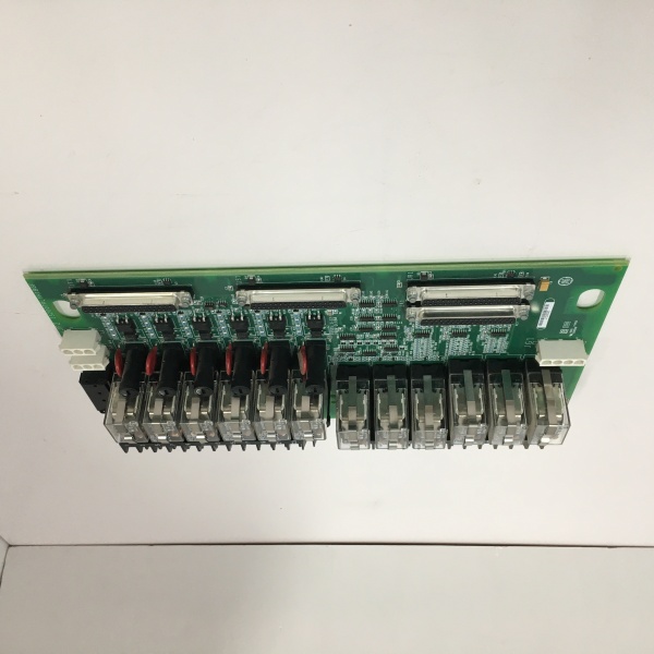
The is a passive terminal board residing in the Exciter Control Cabinet, specifically for EX2100/EX2100e systems. It functions as the field-facing I/O hub for one control processor (Simplex mode, denoted by ‘H3’).
Upstream, it connects to the active controller (e.g., EROC or VSVO processor) via HSLA (High-Speed Serial Link) daughter boards plugged directly onto the ESYS PCB (using the 6 sub-D pin connectors). This handles the noisy serial comms for real-time excitation data. Downstream, it terminates the heavy field wiring: Generator Potential Transformers (PTs) for voltage feedback and Current Transformers (CTs) (1A or 5A) for current feedback. It also hosts two heavy-duty Trip Relay outputs (Form-C), typically used to drive customer lockout devices or interface with the turbine’s TRLY trip chain. Unlike the TMR versions (H1/H2), the H3 is a standalone unit. It sits at Level 1/2, bridging the 125V/250V field instrumentation to the low-voltage logic of the excitation rack.
IS200TRLYH1B
Core Technical Specifications
- Architecture: Simplex (Single Channel, H3 Group Variation)
- Field Inputs: 2x Gen CT (1A/5A), 2x Gen PT (3-Phase, Configurable)
- Auxiliary Inputs: 7x Contact Inputs (24/48/125V DC Wetting)
- Relay Outputs: 2x Form-C (Trip/Security), Rated for 125V DC Coil Drive
- Interface: 6x Sub-D Connectors (For HSLA/Comm Daughter Cards)
- Power Input: 55 V DC (Derived from EPDM or System Supply)
- Signal Conditioning: Onboard Isolation Transformers (CT/PT Galvanic Isolation)
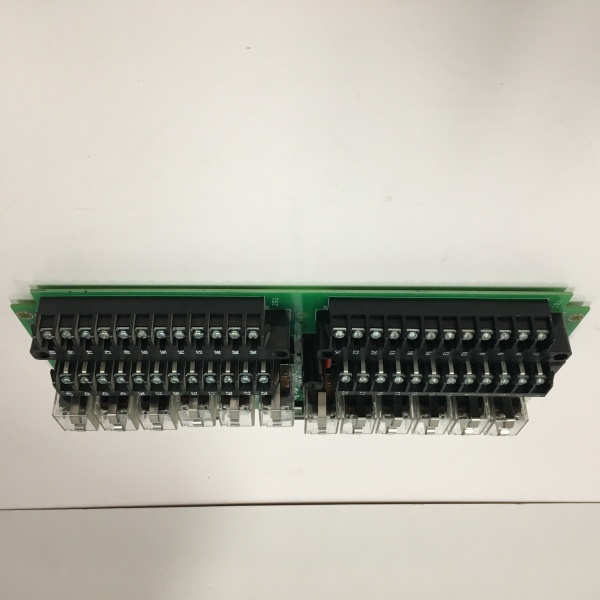
- Terminals: Screw-Type Barrier Strips (Accept #12 – #24 AWG)
- Mounting: Chassis Mount (Exciter Cabinet) or DIN Rail (via adapter)
- Environmental: 0°C to +60°C, Conformal Coated (AAA Revision)
Customer Value & Operational Benefits
Consolidated Excitation I/O
This board kills the need for separate CT/PT terminal boxes and relay interposing panels in the exciter cabinet. By integrating Generator Metering (PT/CT) and Trip Relays on one PCB, it shrinks the panel footprint by 30-40%. For retrofit jobs squeezing an EX2100e into an old GE EX2000 cabinet, this density is the difference between a clean install and a wire-loom nightmare.
Galvanic Isolation for Metering
The onboard Isolation Transformers for CT/PT inputs are critical. Excitation systems are electrically noisy (thyristor switching, 1000A+ field currents). These transformers block ground loops and transient spikes from the generator stator, ensuring your AVR (Automatic Voltage Regulator) sees a clean voltage sine wave. This prevents erratic VAR hunting or spurious over/under frequency trips during grid disturbances.
Simplex MTTR
For non-redundant auxiliaries (e.g., a hydro plant’s static exciter), the Simplex ‘H3’ design means you aren’t paying for two extra processors you don’t need. If this board fails (usually a relay contact weld), you swap the 5k processor pack. It cuts spare parts inventory cost by 60% for single-unit applications.
Field Engineer’s Notes (From the Trenches)
The “Gotcha” on the ESYS series is CT Polarity and Burden. The onboard CT inputs are precision devices. If you land the Generator CT “P1/P2” backwards, your VAR sharing will be 180 degrees out of phase, causing the unit to fight the grid (reactive instability).
Always short the CT secondaries (TB terminals) with a jumper wire beforedisconnecting live wires; an open-circuited CT on a 5A circuit will try to explode the ESYS’s input transformer.
Also, Torque those Trip Relay terminals. The “H3” usually drives the final lockout. A loose “Common” on K1 relay means your Overspeed Trip executes locally but fails to drop the field breaker because the contact didn’t close. Use a 0.6 Nm driver. And check the HSLA daughter card seating—vibration cracks the header solder joints on the ESYS motherbard; if comms are flaky, reflow the header pins before blaming the processor.
IS200TRLYH1B
Real-World Applications
- Static Exciter for Gas Turbine Generator: The ESYSH3AAA terminates the 3-phase PTs (13.8kV:120V) and 5A CTs from the generator stator. It feeds this to the EX2100e controller for AVR logic. Output Relay 1 drives the Field Breaker Trip coil; Output Relay 2 drives the Firing Circuit Inhibit during a distrubance.
- Hydro Plant Voltage Regulation: Simplex excitation control for a 50MW hydro unit. The board handles the “Manual/Auto” selector switch inputs (Aux Contacts) and provides the 4-20mA output drivers (via the HSLA link) to the station annunciator panel indicating “Excitation Loss.”
High-Frequency Troubleshooting FAQ
Q: ToolboxST shows “Loss of HSLA Link” or “Exciter Offline” but the controller CPU is running.
A: Check the HSLA Daughter Card seated on the ESYS board. The 6 sub-D connectors (JX1-JX6) are prone to vibration fatigue. Reseat the HSLA card (usually plugs vertically onto the ESYS). Also, verify the 55V DC supply at the ESYS terminals; if the EPDM (Power Distro) fuse is blown, the HSLA has no power to talk to the processor, even if the CPU is fine.
Q: Generator VARS are reading negative (leading) when they should be lagging.
A: You have a CT Phase Reversal on the ESYS inputs. Swap the “P1” and “P2” leads on one of the CT input terminals (TB1/TB2). Do not swap PTs. Verify phase rotation (A-B-C) matches the PT inputs. Use a power quality meter at the ESYS terminals to confirm Watt/VAR sign before closing the field breaker.
Q: The Trip Relay (K1/K2) clicks, but the Field Breaker doesn’t trip.
A: Check the ESYS Jumper Configuration for the relay outputs. The “H3” has jumpers to select “Wet” (external 125V) vs “Dry” contacts. If your breaker coil is 125V DC but the jumper is set for “Dry,” you’re just opening/closing a floating node. Set jumpers for “Wetting Voltage” matching your trip bus (usually 125V DC) and verify continuity across the N/C or N/O contacts with a multimeter while commanding the test.
Please note: The listed price is not the actual final price. It is for reference only and is subject to appropriate negotiation based on current market conditions, quantity, and availability.


